Surface-mounting coil component and method of producing the same

a technology of surface mounting coil and component, which is applied in the direction of transformer/inductance coil/winding/connection, inductance with magnetic core, etc., can solve the problems of flanges also having inconvenience of cracks, cost reduction, and height reduction, so as to reduce height, low cost, and durability

Active Publication Date: 2007-04-24
TAIYO YUDEN KK
View PDF7 Cites 69 Cited by
  • Summary
  • Abstract
  • Description
  • Claims
  • Application Information

AI Technical Summary

Benefits of technology

[0015]One aspect of the invention provides a surface-mounting coil component which concurrently realizes low cost, reduction in height, and durability demanded in the heat cycle test.
[0032](1) the current corresponding coil having a desired inductor characteristic in spite of requiring low cost and low height,
[0033](2) the surface-mounting coil component having the resin coating material with magnetic powder filled on the outer circumference of the winding wound around the winding core and in the space between the upper flange and the lower flange, in which the resin coating material with magnetic powder has the glass transition temperature of about −20° C. or lower, more preferably about −50° C. or lower in the course of transferring from the glass state to the rubber state during changing of shear modulus with respect to temperature as the physical property when hardening, whereby the flanges can be prevented from cracking in the heat cycle test, and therefore the surface-mounting coil component are suited to being mounted and served on the board housed inside of the portable electronic machinery being subjected to severe changing in circumstances of serving temperatures, and
[0034](3) the surface-mounting coil component having the step of filling the paint of the resin coating material with magnetic powder on the outer circumference of the winding wound around the winding core and in the space range defined between the upper flange and the lower flange in opposition to said upper flange being disposed on the outer circumference of the winding wound around the winding core, being about 0.35 mm or less in thickness, and having a value of about 1.9 or more of the ratio L2 / L1 of an outside dimension L2 of the upper flange to the diameter L1 of the winding core of the drum-type ferrite core, and the step of hardening the paint of the resin coating material with magnetic powder, where the step of filling the paint of the resin coating material with magnetic powder uses the paint of the resin coating material with magnetic powder having the glass transition temperature of about −20° C. or lower in the course of transferring from the glass state to the rubber state during changing of shear modulus with respect to temperature as the physical property when hardening, thereby to decrease the thermal stress owing to the expanding and shrinking behavior of the resin generated in the hardening and heating course after coating the resin in the production process and prevent the flanges of the drum-type ferrite core from breakage. Consequently, it is possible to produce the surface-mounting coil component having high reliability to changing in circumstances of serving temperatures at higher yield.

Problems solved by technology

Since this type appears similar to the structure of a closed magnetic circuit, although it is advantageous in the coil characteristics (in particular, L: inductance), it is disadvantageous in cost and reduction in height since more number of parts are required.
Further, in the producing process, due to hardening and shrinking of the resin coating material with magnetic powder when filling and hardening this resin on the outer circumference of the winding wound around the winding core between the flanges of the drum-type ferrite core, the flanges also had inconvenience of cracks occurring.

Method used


Image

  • Surface-mounting coil component and method of producing the same
  • Surface-mounting coil component and method of producing the same
  • Surface-mounting coil component and method of producing the same

Examples


Embodiment Construction

[0041]Explanation will be made on embodiments of the invention, referring to the attached drawings.

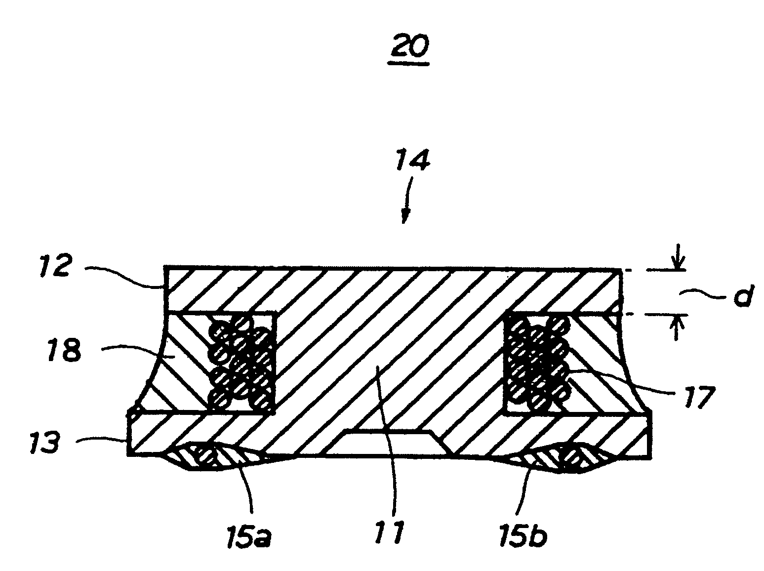
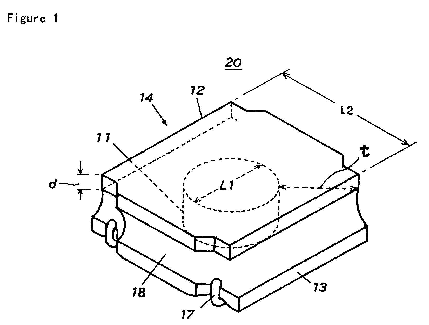
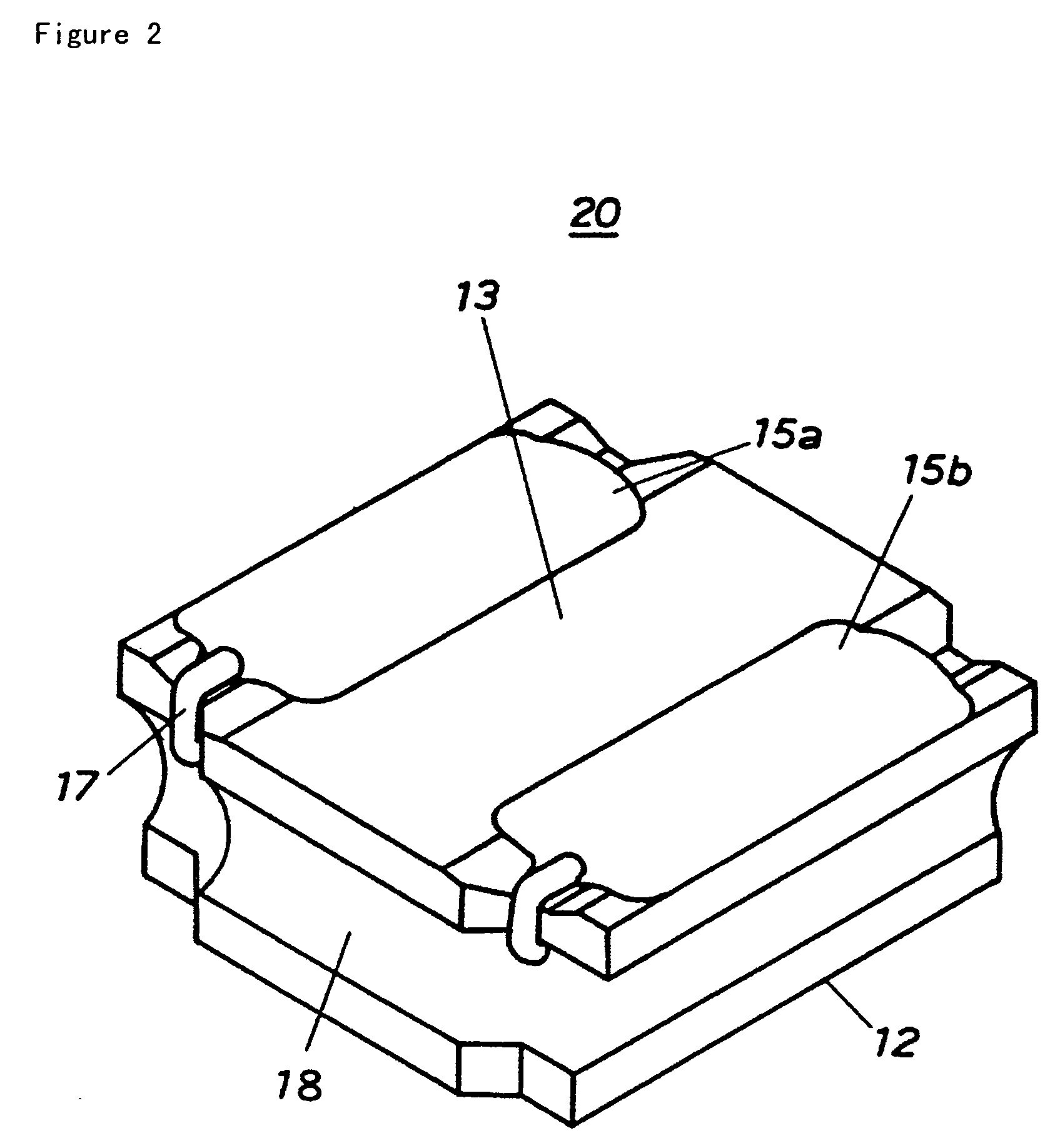
[0042]FIG. 1 is a perspective view seen from the top showing the structure of the face-mounting choke coil that is a typical surface-mounting coil component according to one embodiment of the invention, FIG. 2 is a perspective view seen from the bottom showing the structure of the face-mounting choke coil according to one embodiment of the invention, FIG. 3 is a front view of the face-mounting choke coil according to one embodiment of the invention, and FIG. 4 is a vertical cross-sectional view of the face-mounting choke coil according to one embodiment of the invention.

[0043]In FIGS. 1 to 4, the surface-mounting choke coil 20 has the drum-type ferrite core 14, at least one couple of core-directly attached external electrodes 15a, 15b provided on the lower surface of the lower flange 13 of the drum-type ferrite core 14, and the winding 17, the drum-type ferrite core being composed of t...


PUM

PropertyMeasurementUnit
glass transition temperatureaaaaaaaaaa
thicknessaaaaaaaaaa

Abstract

A surface-mounting choke coil has a resin coating material with magnetic powder which is filled a space between the upper flange and the lower flange of a drum-type ferrite core, while covering the circumferential of the winding. The resin coating material with magnetic powder has a glass transition temperature Tg of about −20° C. or lower, more preferably about −50° C. or lower in a course of transferring from a glass state to a rubber state during changing of shear modulus with respect to temperature as a physical property when hardening, and the thickness of the upper flange of the drum-type ferrite core is about 0.35 mm or less, and a value of a ratio L2 / L1 of an outer diameter L2 of the upper flange to a diameter L1 of the winding core of the drum-type ferrite core is about 1.9 or more.

Description

BACKGROUND OF THE INVENTION[0001]1. Field of the Invention[0002]The present invention relates to a surface-mounting coil component applied, for example, to coils for heightening and lowering voltage of DC / DC source of portable electronic devices.[0003]2. Description of the Related Art[0004]A current corresponding coil (such as choke coil) for application to DC / DC power source of the portable electronic devices such as portable telephones or digital still cameras has been in particular demanded to have a surface-mounting coil component of low height in an external dimension while securing a desired inductor characteristic.[0005]The portable electronic device is usually carried around and subjected to severe changing of circumstances in temperatures, and therefore a surface-mounting coil component mounted on a board housed inside of the portable electronic device is imposed heat cycle tests of 10 cycles at −25° C. to +85° C., or most severely, 10 cycles at −40° C. to +85° C.[0006]As r...

Claims


Application Information

Patent Timeline
Patent Type & Authority Patents(United States)
IPC IPC(8): H01F27/02H01F5/00H01F27/32H01F17/04H01F17/06H01F27/255H01F27/28H01F27/29H01F37/00H01F41/00
CPCH01F17/045H01F27/292H01F27/027Y10T29/49071Y10T29/4902Y10T29/49073H01F2017/048
Inventor KUROIWA, KATSUTOSHIIGUCHI, KOICHIKASHIWA, TOMOOOKAMOTO, MASAKISAMATA, TAKAHIRO
Owner TAIYO YUDEN KK
Why Eureka
Try Eureka