
RFID tag with visual environmental condition monitor

a technology of environmental condition monitor and RFID tag, which is applied in the direction of burglar alarm mechanical actuation, camera filter, instruments, etc., can solve the problems of inability to provide product id information to the device, and inability to provide the benefits of RFID tag or label

Active Publication Date: 2007-04-24
TEMPTIME CORP
View PDF24 Cites 106 Cited by
  • Summary
  • Abstract
  • Description
  • Claims
  • Application Information

AI Technical Summary

Benefits of technology

The present invention provides an RFID tag with a simple and economic means for detecting and reporting an environmental condition. The RFID tag is designed to be associated with a host product and includes a data memory to receive data about the host product and a transponder to transmit the data to an external interrogator in response to interrogation. The RFID tag also includes a visual indicator that can detect and provide a visual indication of the environmental condition experienced by the host product. The visual indicator can be easily read by a visual inspector and can provide a useful indication of the host product's condition. The invention can be used with a variety of perishable host products and can help improve product safety and freshness.

Problems solved by technology

's proposed device is complex requiring a number of electrical components, and lacks provision on the device for product ID information.
Thus, known environment-condition reading devices intended for tags or labels fail to provide the benefits of RFIDs, may be unduly costly, or complex and may have other drawbacks.
Passive devices lack their own power source and derive energy from the RF signal used to interrogate the RFID tag.
's and Brollier 's are complex, expensive and potentially cumbersome, and accordingly are unsuitable for certain applications.

Method used


Image

  • RFID tag with visual environmental condition monitor
  • RFID tag with visual environmental condition monitor
  • RFID tag with visual environmental condition monitor

Examples


Embodiment Construction

[0039]The following more detailed description of the invention is intended to be read in the light of, and in context with, the preceding summary and background descriptions but without being limited by the preceding descriptions.

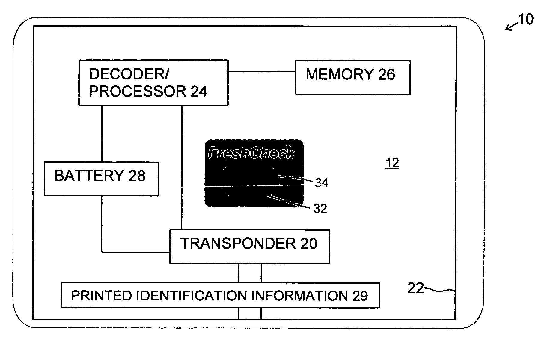
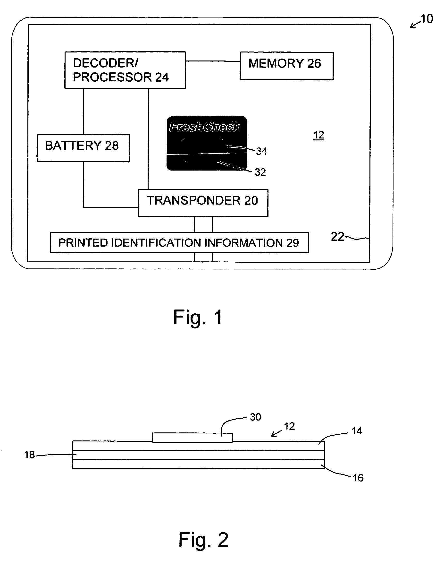
[0040]Referring to FIG. 1, one exemplary embodiment of condition-sensing RFID tag 10 useful in the practice of the present invention comprises a rectangular laminate label 12 of plastic, card or other suitable material. Label 12 comprises protective upper and lower plastic sheet layers 14 and 16 respectively which sandwich a printed circuit 18 providing RFID functionality in an intermediate layer.

[0041]Printed circuit 18 comprises an analog transponder 20, to detect and decode an RF interrogation signal, an antenna 22 to receive and transmit the signal and a decoder-processor 24 to execute the RFID functions and provide analog-digital conversion for communication with transponder 20. Printed circuit 18 further comprises memory 26 to store data which can be ...


PUM


Abstract

A combination RFID tag intended to be associated with a host product, for example by being secured to the outside of a package containing a perishable product, e.g. foodstuffs or vaccines, which RFID tag is provided with a visually readable environmental condition exposure indicator. The visual indicator can sense the exposure of the RFID tag to an environmental condition e.g. temperature, experienced by the host product providing a visual indication, e.g. a color change, readable externally of the RFID tag of the sensed environmental condition. The visual indicator can be chemically active, for example an acetylenic agent, and may be responsive to cumulative temperature excursions over time. The novel RFID tag 11 and tag inspection methods of the invention permit an efficacious harnessing of information about the condition exposure history of a specific inventory item including product identification and related data. The information from multiple items can be compiled into a database that may be audited or statistically analyzed to reveal useful information regarding the handling of the items.

Description

STATEMENT REGARDING FEDERALLY SPONSORED RESEARCH OR DEVELOPMENT[0001](Not applicable.)BACKGROUND OF THE INVENTION[0002]The present invention relates to radio frequency identification (“RFID” herein) tags, and more particularly, to an RFID tag provided with means to detect and externally report information regarding an environmental condition.[0003]Many different devices are known for marking, labeling, tagging or otherwise associating information with a host product regarding matters such as the identity, source, nature, price and / or other characteristic of the product. Such information is useful to inform consumers, end users, distributors, manufacturers and others who may handle, inspect or merely encounter commercial and other products distributed in a modern society.[0004]Such known devices include printed text or graphic labels and tags of paper, card, plastic or metal which may be attached to a host product by various means such as adhesive, stitching, ties, rivets, or other f...

Claims


Application Information

Patent Timeline
Patent Type & Authority Patents(United States)
IPC IPC(8): G08B13/14
CPCB65D79/02G01K3/04G06K19/0717G06K19/0723B65D2203/10
Inventor MARTINGRABINER, FREDERICK R.
Owner TEMPTIME CORP
Learn More