
Blast MIMO signal processing method and apparatus

a signal processing and blasting technology, applied in the field of communication, can solve the problems of limiting its use, affecting the complexity or cost of the transceiver, and corruption or loss of the information borne by the image,

Active Publication Date: 2007-04-24
MARVELL ASIA PTE LTD
View PDF11 Cites 31 Cited by
  • Summary
  • Abstract
  • Description
  • Claims
  • Application Information

AI Technical Summary

Benefits of technology

[0015]Another aspect of the present invention is directed to successive interference cancellation which employs Multi-Staged Nested Weiner Filtering (MSNWF) to recover soft estimates of the transmitted component-symbols from the vector observed at the BLAST MIMO receiver. Employing MSNWF estimation consistent with this aspect of the present invention is believed advantageous in that it avoids the need for matrix inversion operations involving the estimated channel matrix. Consistent with the disclosed embodiments, Covariance Level Order Recursive-MSNWF (MSNWF-COR) or MSNWF Conjugate Gradient techniques may be conveniently employed in this MSNWF estimation.

Problems solved by technology

In conventional wireless systems, multipath represents a significant impediment to accurate transmission, because the images can arrive at the receiver at slightly different times, causing destructive intersymbol interference and leading to corruption or loss of the information borne by these images.
However, the complexities involved in implementing D-BLAST space-time coding currently limits its use to situations where maximum spectral efficiency is required, without regard for transceiver complexity or cost.
However, unlike D-BLAST, no inter-substream space-time coding is performed, resulting in a much simpler and practical vector encoding process for the outbound datastream.
It should be appreciated that matrix inversion is a computationally complex and expensive operation and therefore not very attractive to implement though hardware, including application specific integrated circuits (ASICs).

Method used


Image

  • Blast MIMO signal processing method and apparatus
  • Blast MIMO signal processing method and apparatus
  • Blast MIMO signal processing method and apparatus

Examples


Embodiment Construction

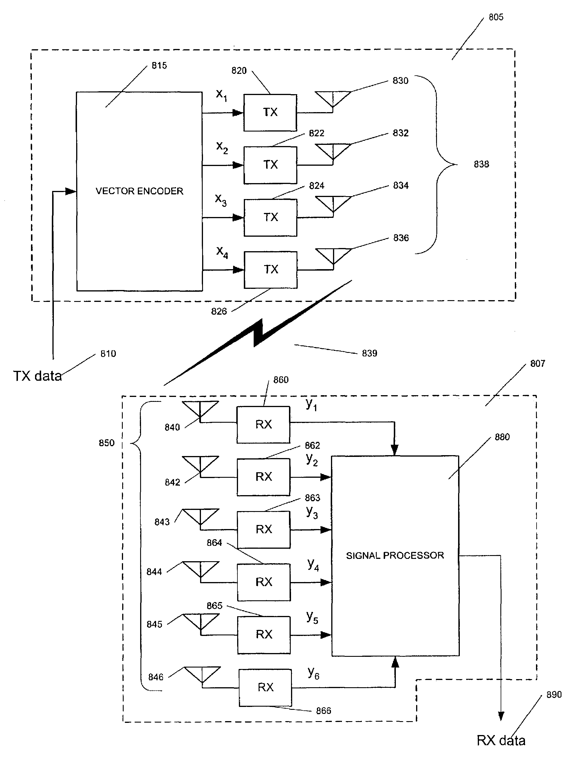
[0027]A high level block diagram of a MR=6, MT=4 BLAST MIMO communication system according to an embodiment of the present invention is shown in FIG. 6. This communication system includes BLAST transmitter unit 805 and BLAST receiver unit 807. As with known BLAST systems, the capacity of the BLAST MIMO communication system shown in FIG. 6 is dependent on the number of transmit antennas being utilized. However, it should be realized that this number (four) shown here has been selected for illustration purposes only and in fact any combination of transmitter-antenna and receiver-antenna-pairs may be exploited without departing from the scope of the present invention as long as the number of receive antennas is at least equal to the number of transmit antennas being used for a given communications link.

[0028]The BLAST transmitter unit 805 is generally similar in configuration and operation to a conventional V-BLAST transmitter. As such, a single discreet datastream 810 is demultiplexed...


PUM


Abstract

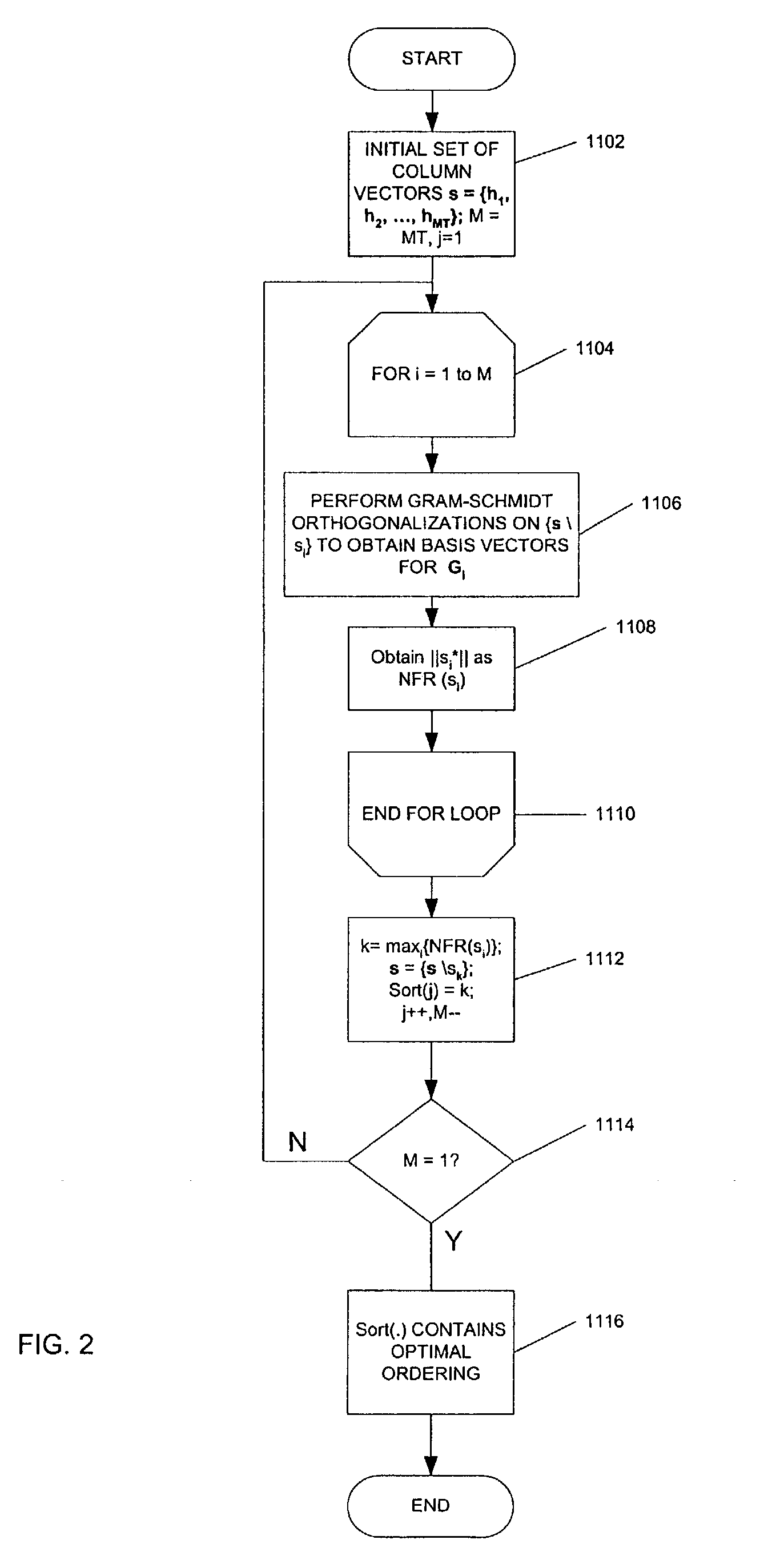
A technique for generating a demodulation ordering used in receive signal processing operations in a BLAST MIMO receiver that is based on a relative comparison of near-to-far resistance measures among vectors forming the estimated channel transfer function matrix is disclosed. This near-to-far resistance comparison provides a resulting demodulation ordering believed equivalent to that provided by conventional V-BLAST techniques without requiring computation of the pseudoinverse of the estimated channel matrix. Also disclosed is a successive interference cancellation technique which employs Multi-Staged Nested Weiner Filtering (MSNWF) to recover soft estimates of the transmitted component-symbols from the vector observed at the BLAST MIMO receiver. Employing such MSNWF estimation is believed advantageous in that it avoids the need for matrix inversion operations involving the estimated channel matrix, Covariance Level Order Recursive-MSNWF (MSNWF-COR) or MSNWF Conjugate Gradient techniques may be conveniently implemented to provide the desired MSNWF estimation.

Description

RELATED APPLICATION[0001]This application claims priority benefit under 35 U.S.C. § 119(e)(1) of and incorporates by reference U.S. Provisional Application No. 60 / 433,272, filed on Dec. 12, 2002, entitled “A COMPUTATIONALLY EFFICIENT ARCHITECTURE FOR LAYERED-MMSE EQUALIZER FOR MULTIUSER COMMUNICATIONS”, which is incorporated herein fully by reference.TECHNICAL FIELD[0002]This invention is generally directed to communications, and is more particularly concerned with observed signal processing in Bell Labs Layered Space-Time or BLAST type Multiple Input Multiple Output (MIMO) communications.BACKGROUND OF THE INVENTION[0003]Multiple Input Multiple Output (MIMO) systems are becoming popular in wireless and wireline communications to leverage aspects of intersymbol interference to potentially increase the bandwidth efficiency of existing spectra. In the case of wireless systems, radio waves do not propagate simply from transmit antenna to receive antenna, but bounce and scatter randomly ...

Claims


Application Information

Patent Timeline
IPC IPC(8): H04B15/00
CPCH04L1/0631H04L1/0656
Inventor SHIRALI, KEDAR
Owner MARVELL ASIA PTE LTD
Learn More