System and method for loading a cargo space with piece goods

a cargo space and piece goods technology, applied in the direction of wrapping/bundling articles, packaging goods, pile separation, etc., can solve the problems of inability to fully automate the loading system with which the above described are applied, inability to load multi-side-closed containers at present, and the loss of piece goods, so as to avoid damage or loss of piece goods and reduce the loading time for the entire loading process.

Inactive Publication Date: 2007-05-01
KUKA INNOTEC
View PDF17 Cites 33 Cited by
  • Summary
  • Abstract
  • Description
  • Claims
  • Application Information

AI Technical Summary

Benefits of technology

[0009]The problem of the invention is to provide an installation for loading piece goods into a loading space preferably having an at least partly deformable piece good surface, with a feed device on which the piece goods can be individually fed and a transfer device onto which the piece goods can be transferred from the feed device and by means of which the piece goods can be brought into the interior of the loading space and which is so further developed that the loading space can be filled between the piece goods preferably deposited in stack-like manner within the loading space. It must in particular be possible to convey and handle piece goods, whose piece good surface is at least partly flexible, such as e.g. sacks filled with bulk material, e.g. sand, cereal or sugar sacks, in such a way that on the basis of a predetermined loading plan, they can be deposited in space-optimized manner within the loading space with a view to avoiding the aforementioned gaps. It must also be ensured that the loading process takes place securely and safely in order to avoid damage or losses to the piece goods to be loaded. The loading time for the entire loading process is also to be reduced compared with known loading procedures.
[0011]This makes it possible to significantly increase the degree of filling of the loading space filled with the individual piece goods. As a result of an automated transfer into the loading space of in part compressed, individual piece goods which are optimized as regards their degree of filling, no further loading aids are needed, which remain within the loading space and therefore take up valuable loading volume. Instead the individual piece goods are brought in layer form (two-dimensional) or block wise (three-dimensional) into the loading space and are deposited there whilst forming substantially self-stabilizing piece good stacks. As a result of the possibility of fully automatic loading of the loading space through lateral or frontal insertion of space shape-compressed piece goods arranged in layers into multiside-closed loading spaces, the costs associated with the loading process can be significantly reduced and in particular no labor force is required for transferring the piece goods into the loading space.
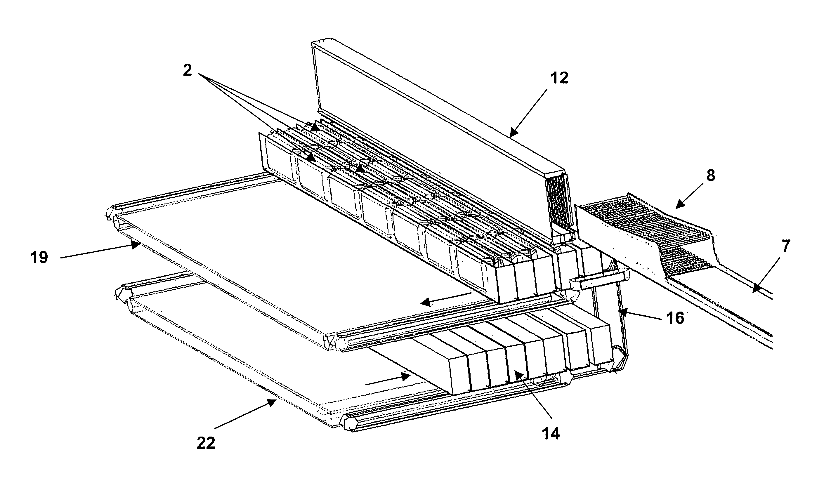
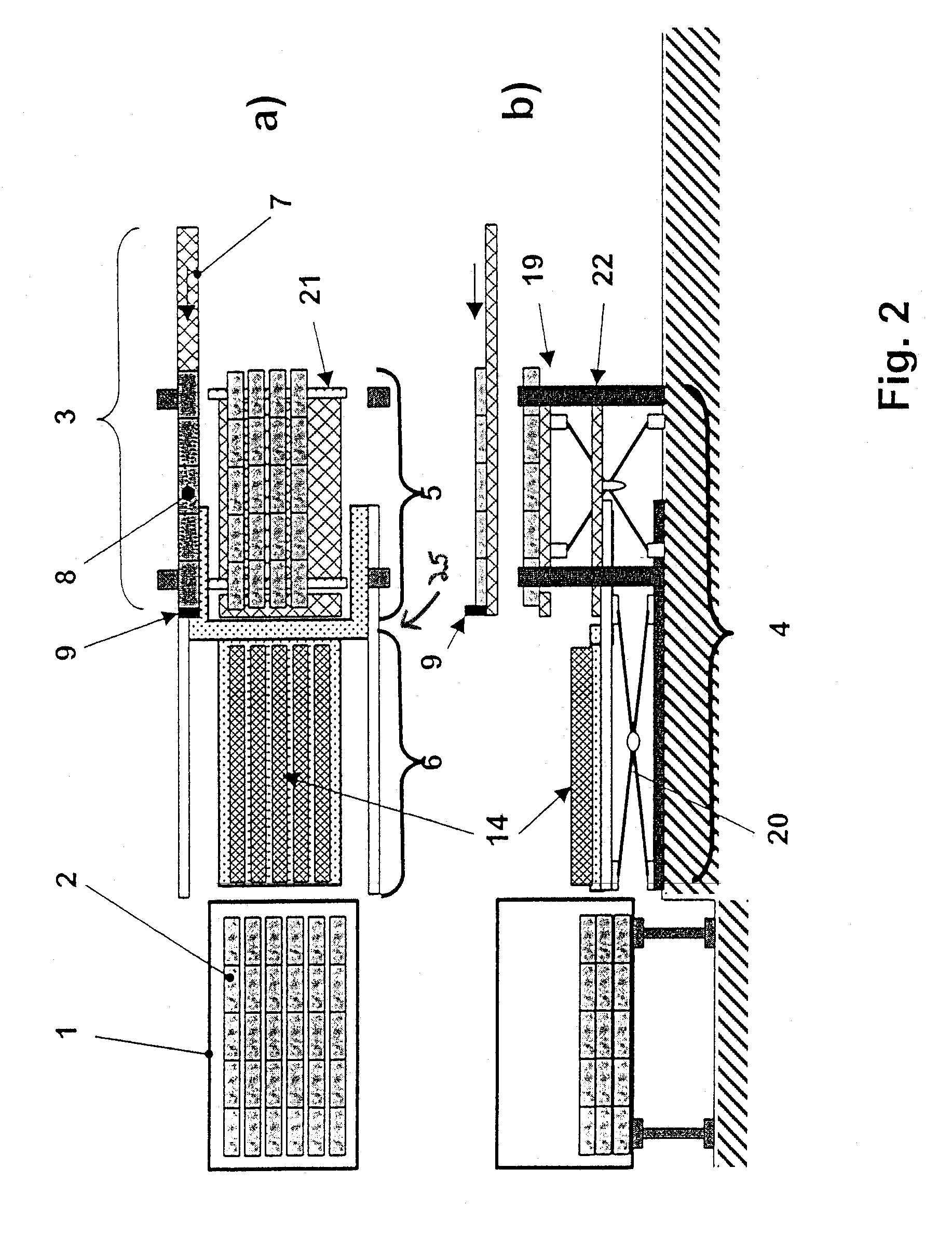
[0023]The loading means are then retracted from the loading space in opposition to the conveying direction and at the same time the holding means of the separating unit prevent the piece good rows inside the individual loading means from being extracted together with the latter from the loading space again. Instead the individual piece goods are shoved out of the loading means along a piece good row relative to the particular loading means using a “cake server principle” and are consequently deposited on the loading space bottom or floor. By omitting the external mechanical pressure acting on the piece goods within the loading means the piece goods brought out of the latter expand slightly as a result of their own weight and inherent deformability, so that they come into mutual contact in a layer-like arrangement and are able to stabilize one another.
[0025]As a result of the inventive, planned, external force action on the piece goods to be loaded up to the instant where the individual piece goods are deposited in layer form for forming piece good stacks within the loading space it is ensured that the piece goods have an optimum, stackable space shape, which utilizes the available loading volume substantially without any formation of space-wasting gaps between two adjacent piece goods. The reduction of the gaps within the stack pattern of the piece goods also leads to an increase in the friction surfaces between the individual piece goods, so that the frictional force acting between the piece goods is increased and at the same time the stability of the entire piece good stack deposited within the loading space is improved.

Problems solved by technology

Apart from the in part very high dead weight of the individual piece goods, it is not possible with such a partially manual loading or only through the application of very high effort to stack piece goods to just below the loading space top or roof, particularly as the loading space height generally exceeds the manually accessible working height.
Completely automated loading systems with which the above described, multiside-closed containers can be loaded are not at present available.
In addition, when using the at least partly automated loading procedures, as a result of the only very short time slot within which the loading process must be concluded, it is not possible to ensure the precise maintenance of the desired positions of the individual piece goods established on the basis of a predetermined loading pattern.
As a result the necessary piece good quantity cannot be completely brought into the loading space in many cases.
In particular on loading piece goods packed in sacks, on depositing the individual piece goods undefined geometrical shapes arise, which cause unused gaps within the stack-like piece good arrangement and consequently significantly reduce the degree of filling of the loading space.

Method used


Image

  • System and method for loading a cargo space with piece goods
  • System and method for loading a cargo space with piece goods
  • System and method for loading a cargo space with piece goods

Examples


Embodiment Construction

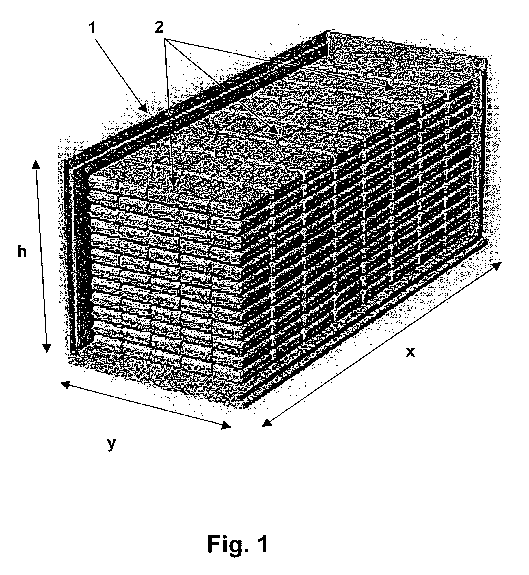
[0040]Referring to the drawings in particular, the object of the installation according to the invention is to bring about an automatic, filling level-optimized, frontal or lateral loading of flexible goods, preferably sand, cereal or sugar sacks, in a multiside-closed loading space. To bring about a maximum space utilization within the loading space, prior to loading the piece goods are brought into an optimum space shape and / or orientation for loading purposes. The stack-like layer patterns producible in this way within the loading space and as can be gathered from FIG. 1, have a minimum of gaps between the stack-like piece goods. It is possible to implement with such preshaped piece goods the palletizing pattern shown in FIG. 1 with x piece goods in the loading space depth, y piece goods in the loading space width and z piece goods in the loading space height. The values x, y and z result from the loading space 1 and the piece good dimensions, whilst taking account of or correspo...


PUM


Abstract

A machining system and unit, especially a welding cell, is provided for use for the machining of workpieces (2), especially body parts of vehicles. The machining system has one or more machining stations (15, 16) with robots (18, 19, 20) and at least one rotation or turning station (5), which has at least two work stations (6, 7) for carrying out different operations simultaneously. The turning station (5) has at least two multiaxially movable turning units (8, 9) arranged next to one another with said gripping tools (11, 12, 13). The working areas (10) intersect each other at the work stations (6, 7).

Description

CROSS REFERENCE TO RELATED APPLICATIONS[0001]This application is a United States National Phase application of International Application PCT / EP03 / 10818 filed Sep. 30, 2003 and claims the benefit of priority under 35 U.S.C. § 119 of German Application DE 102 46 285.2 filed Oct. 2, 2002, the entire contents of which are incorporated herein by reference.FIELD OF THE INVENTION[0002]The invention relates to an installation and a method for loading a loading space with piece goods preferably having an at least partly deformable piece good surface, with a feed device on which the piece goods can be singly fed in, as well as a transfer device onto which the piece goods can be transferred from the feed device and by means of which the piece goods can be brought into the interior of the loading space.BACKGROUND OF THE INVENTION[0003]The industrial dispatch of piece goods by truck, railway, ship or aircraft provides for the use of containers, which are to be loaded and unloaded with respect to...

Claims


Application Information

Patent Timeline
Patent Type & Authority Patents(United States)
IPC IPC(8): B65B1/24B65G63/02B65G67/20
CPCB65G67/20B65G2201/0238B65G2203/044
Inventor COTTONE, NORBERTSIMONS, FLORIAN
Owner KUKA INNOTEC
Why Eureka
Try Eureka