Structures including synchronously deployable frame members and methods of deploying the same

a technology of synchronous deployment and frame members, applied in the field of structures, can solve the problems of increasing the mass moment of inertia, affecting array design and spacecraft performance, and not being suitable for use in deploying other types of flexible blanket members, and achieving the effect of low deployment aspect ratio

Inactive Publication Date: 2007-05-01
NORTHROP GRUMMAN SYST CORP
View PDF29 Cites 37 Cited by
  • Summary
  • Abstract
  • Description
  • Claims
  • Application Information

AI Technical Summary

Benefits of technology

[0010]The present invention is directed to a system and method for deploying a modular structure, including blankets, in space. The structure preferably includes a system of blankets incorporated into a large-area framing structure that is self-deployable in an outward direction as well as across a lateral direction, thereby achieving a low deployment aspect ratio.

Problems solved by technology

This increase in mass moment of inertia is detrimental to array design and to spacecraft performance.
One problem resulting from existing blanket array structures is that they do not permit efficient tiling of individual blankets to produce a large array that satisfies modern power requirements.
Further, existing array structures are designed specifically for deploying solar blankets, and thus are not suitable for use in deploying other types of flexible blanket members, such as synthetic aperture radar blankets, and electromagnetic shielding blankets (e.g., sun shield blankets).

Method used


Image

  • Structures including synchronously deployable frame members and methods of deploying the same
  • Structures including synchronously deployable frame members and methods of deploying the same
  • Structures including synchronously deployable frame members and methods of deploying the same

Examples


Embodiment Construction

[0036]The preferred embodiments will now be described with reference to the drawings. To facilitate description, element numerals designating an element in one figure will represent the same element in any other figure.

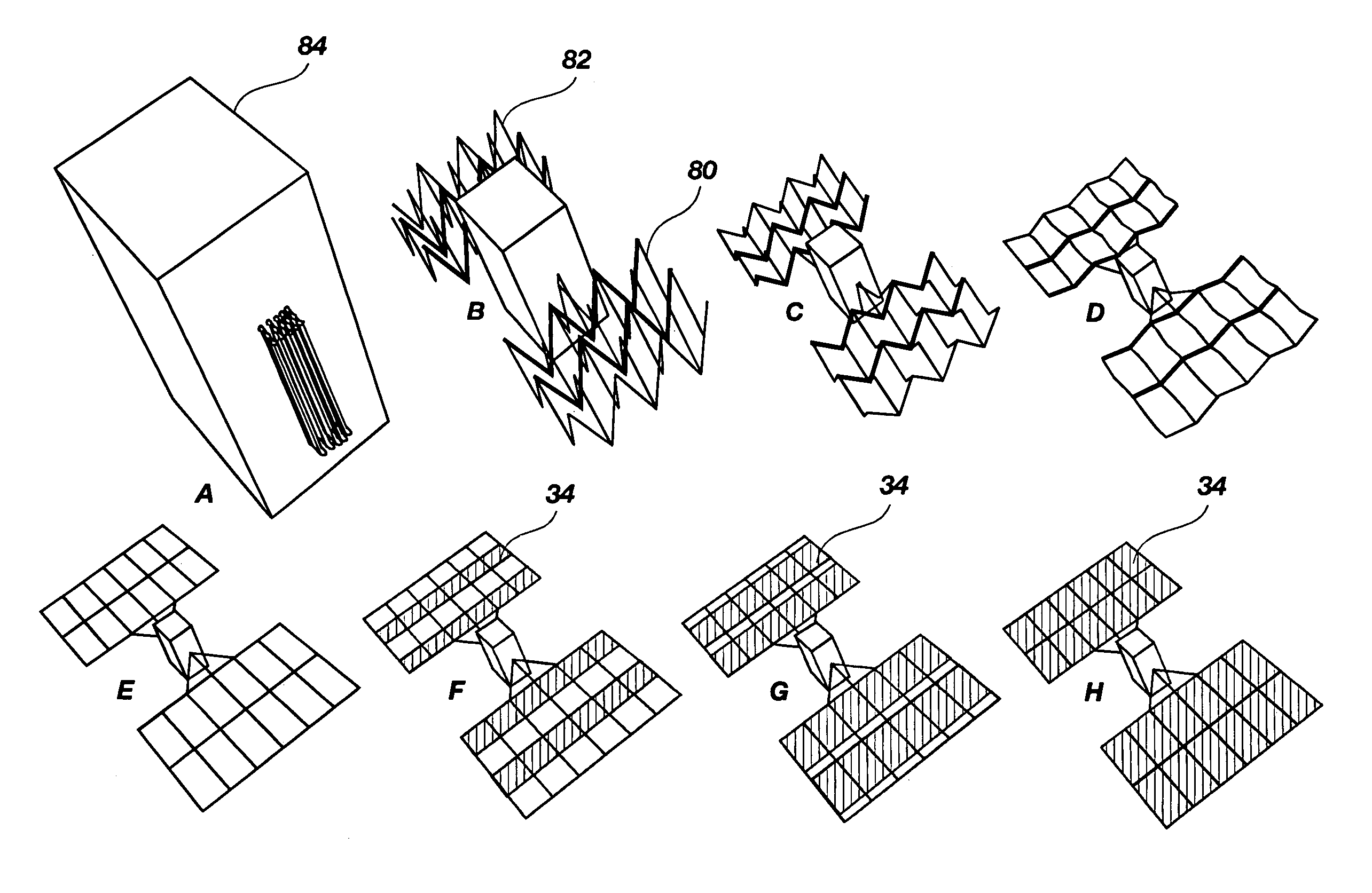
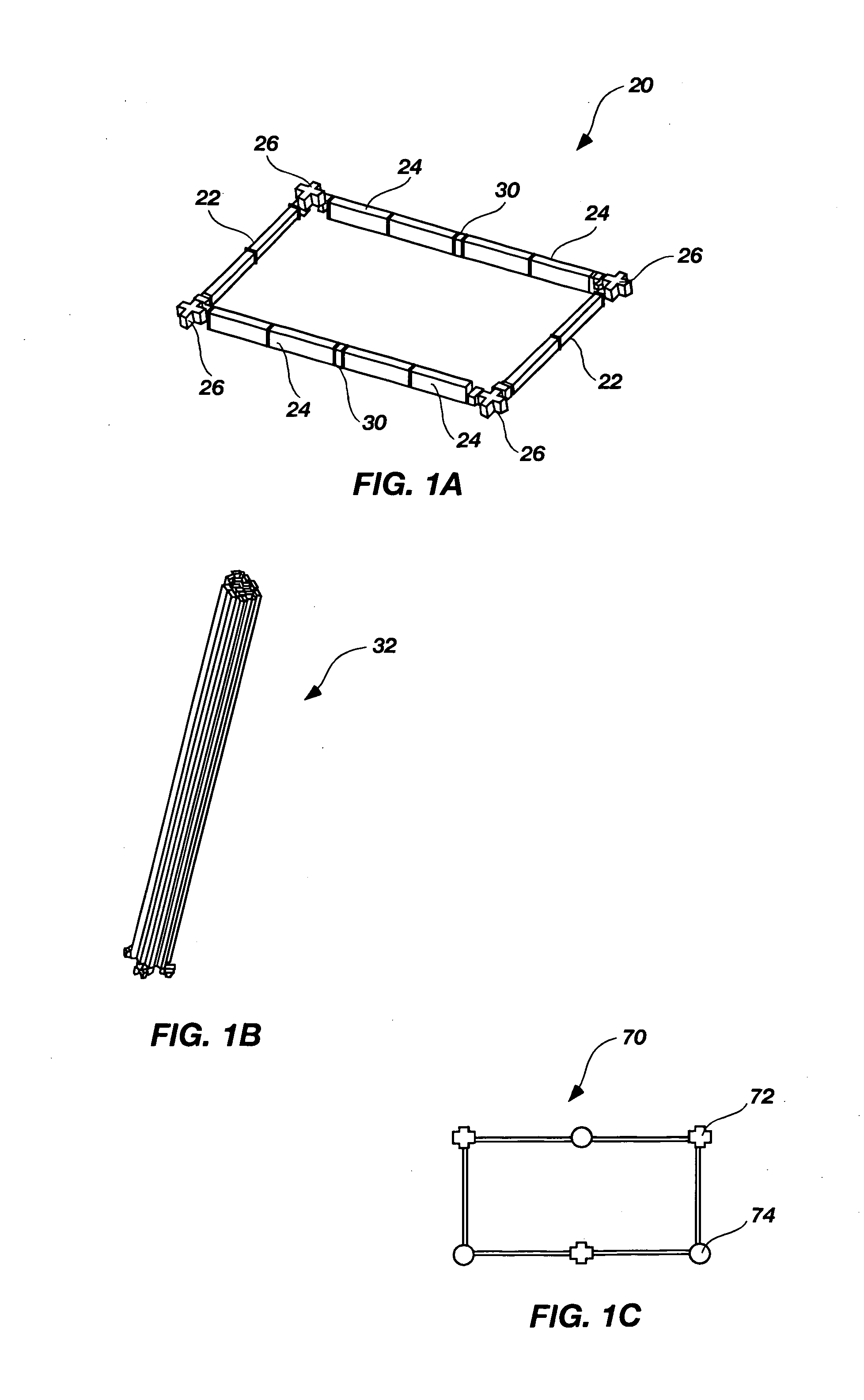
[0037]FIG. 1A is a perspective view of a rectangular, or substantially rectangular, bay structure 20 according to a preferred embodiment of the present invention. The rectangular bay structure 20 is configured to be tiled to one or more other rectangular bay structures, as further described below. Additionally, the rectangular bay structure 20 may be retracted into, and deployed from, a bundle of struts, as further described below.

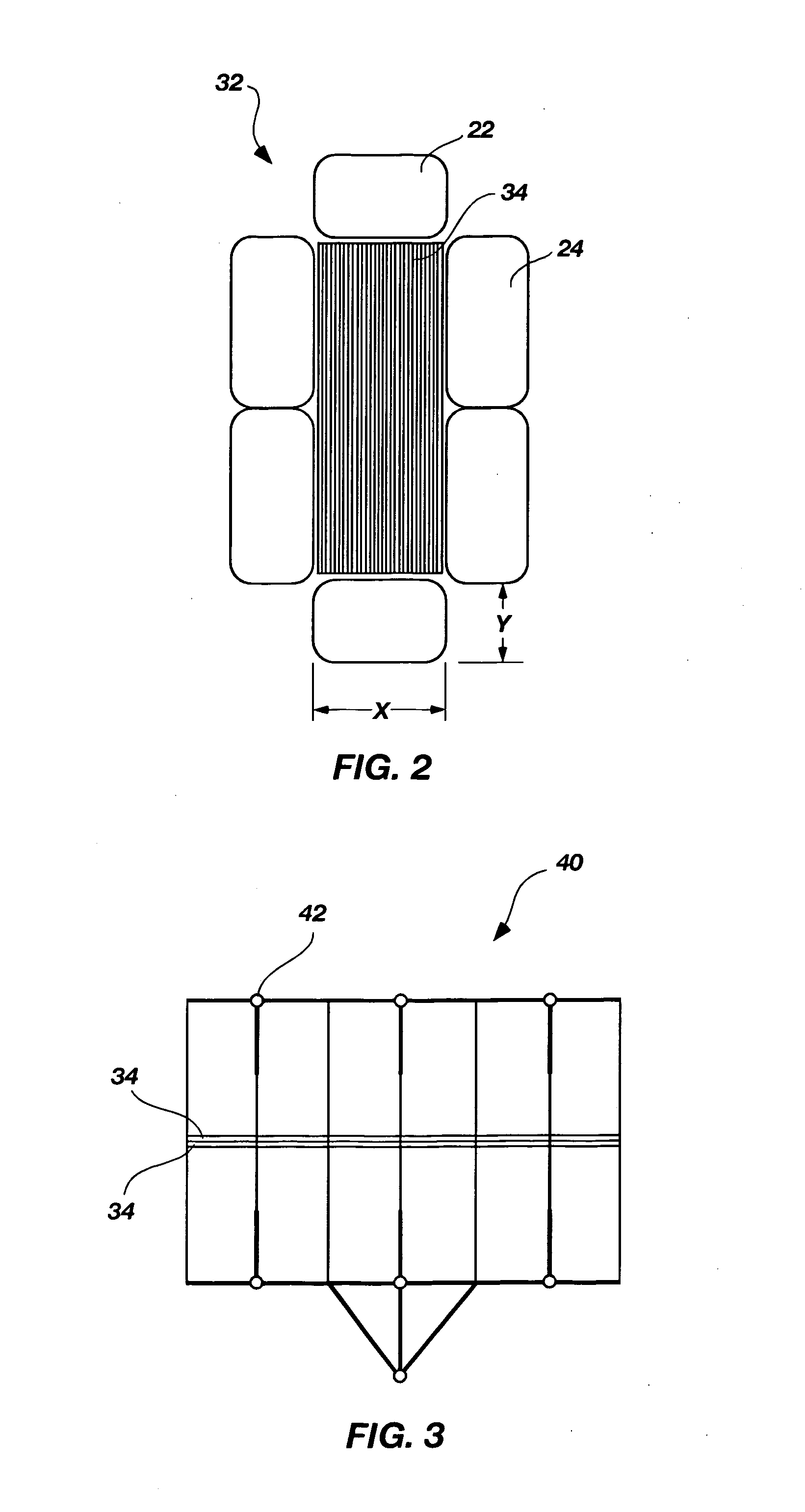
[0038]The rectangular bay structure 20 preferably comprises two arm struts 22 (alternatively referred to as “yards”), or other suitable frame members, located at opposed ends of the rectangular bay structure 20. Each arm strut 22 is preferably connected to a pair of leg struts 24 (alternatively referred to as “spars”), or other suitable fram...


PUM


Abstract

A lightweight structure for space application is deployable from a compact bundle of interconnected struts into a plurality of tiled substantially rectangular bays. Each bay preferably comprises four or six hinged strut members having substantially rectangular cross sections, such that a solar or other suitable blanket may be compactly nested within the bundled struts. In one aspect of the invention, the blanket is attached to two opposed strut members of a six-member strut bundle, such that the blanket is unfolded during deployment of the strut bundle into a substantially rectangular bay. In another aspect of the invention, the blanket is attached to, and held against, a single strut in a strut bundle. After the strut bundle is deployed into a substantially rectangular bay, the blanket is spread across the bay via a cable mechanism or other deployment mechanism.

Description

GOVERNMENT LICENSE RIGHTS[0001]The U.S. Government has a paid-up license in this invention and the right in limited circumstances to require the patent owner to license others on reasonable terms as provided for by the terms of Contract No. F29601-00-C-0144 awarded by the Air Force Research Laboratory.BACKGROUND OF THE INVENTION[0002]The present invention relates generally to structures that are deployable in space, and specifically to structures and methods that are used to deploy areas of flat films, membranes, or blankets.[0003]Deployable array structures for use on spacecraft, satellites, and the like, have been developed in many forms. Generally, solar array structures consist of a plurality of rigid honeycomb panels, which are flat-folded for storage along one dimension, like an accordion pleat, and are extendable outwardly from a spacecraft in a simultaneous or sequential manner. One example of such a configuration of panels is described in U.S. Pat. No. 5,487,791.[0004]A num...

Claims


Application Information

Patent Timeline
Patent Type & Authority Patents(United States)
IPC IPC(8): H01L31/045E04H12/18
CPCH02S30/20H02S20/00Y02E10/50Y10S136/292
Inventor MURPHY, DAVID MICHAEL
Owner NORTHROP GRUMMAN SYST CORP
Why Eureka
Try Eureka