Wireless LAN system and a transmitter-receiver in a wireless LAN system

a wireless lan and receiver technology, applied in the field of local area networks, can solve the problems of large amount of noise generated, system complexity, and inability to secure the bandwidth required for high-speed transmission, and achieve the effect of optimal communication environment, deterioration of communication quality, and optimal antenna directivity characteristi

Inactive Publication Date: 2007-05-01
FUJITSU LTD
View PDF16 Cites 0 Cited by
  • Summary
  • Abstract
  • Description
  • Claims
  • Application Information

AI Technical Summary

Benefits of technology

[0016]Further, after the satellite station starts to exchange data frames as communications with the master station, conditions can be set for the number of errors detected in a data frame that are allowed to be received, or the electric field intensity of the data frame that is allowed to be received, and when the conditions are not met, an optimal antenna directivity characteristic can be determined again. Thus, the deterioration of communication quality occurring because a satellite station or the master

Problems solved by technology

However, since this bandwidth is also used for industrial purposes or electronic ovens, a large amount of noise is generated.
To suppress this large amount of noise it is necessary to employ a spread spectrum communication method, which has made a system complicated.
The system also has a drawback that in this wave range a bandwidth required for a high speed transmission cannot be secured.
However, the wireless LAN system using an electromagnetic wave in a millimeter range has the following problems.
The first problem is that a communication environment rapidly deteriorat

Method used


Image

  • Wireless LAN system and a transmitter-receiver in a wireless LAN system
  • Wireless LAN system and a transmitter-receiver in a wireless LAN system
  • Wireless LAN system and a transmitter-receiver in a wireless LAN system

Examples


Embodiment Construction

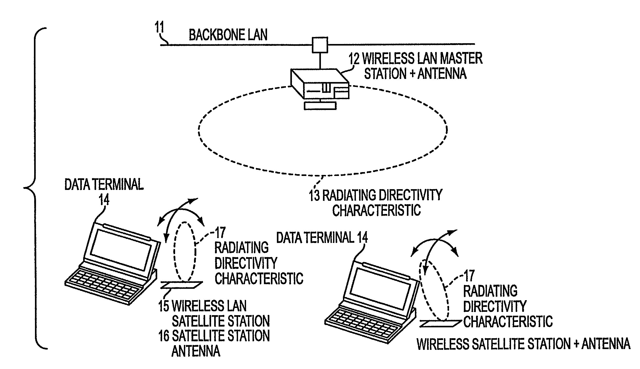
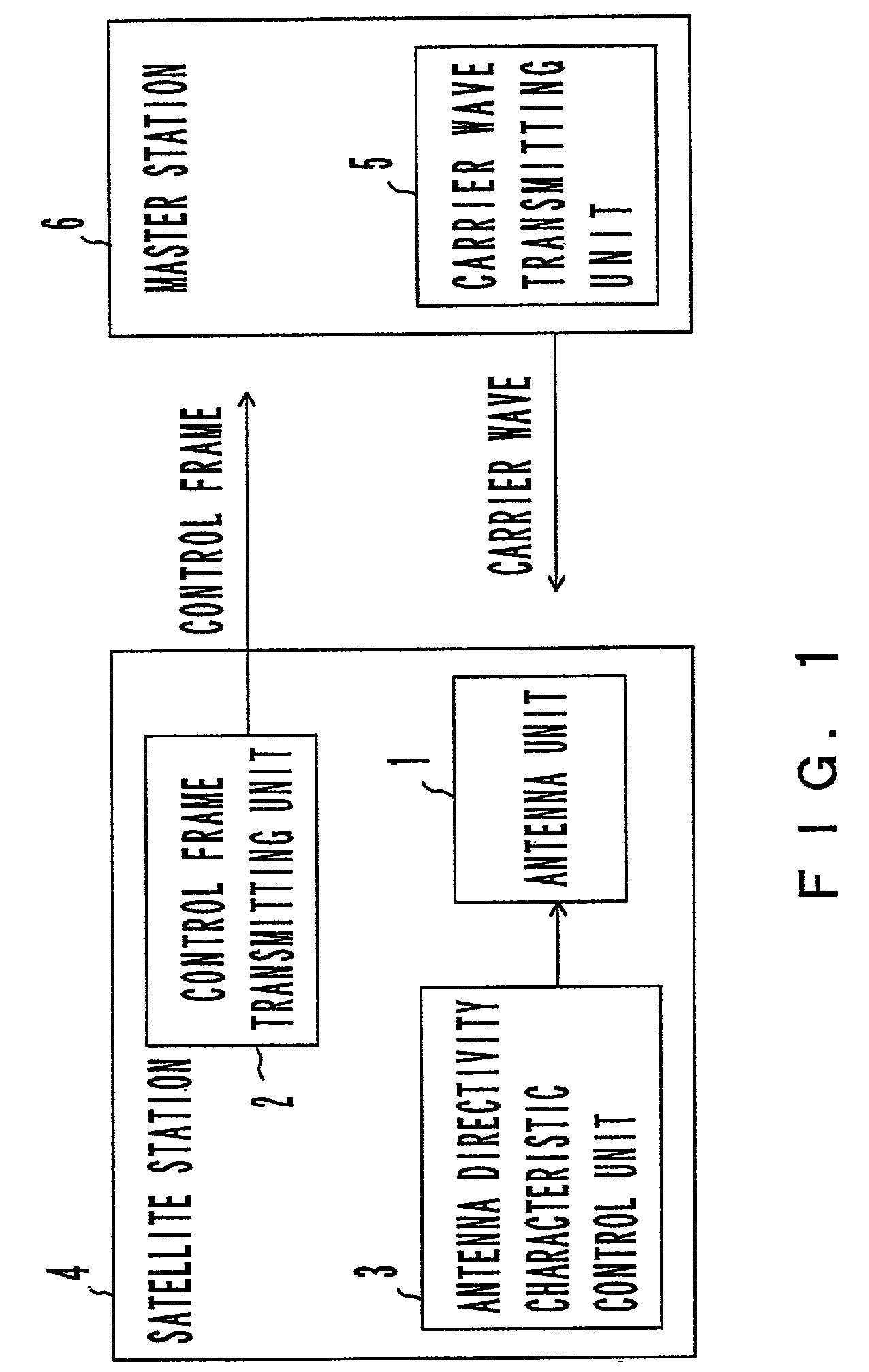
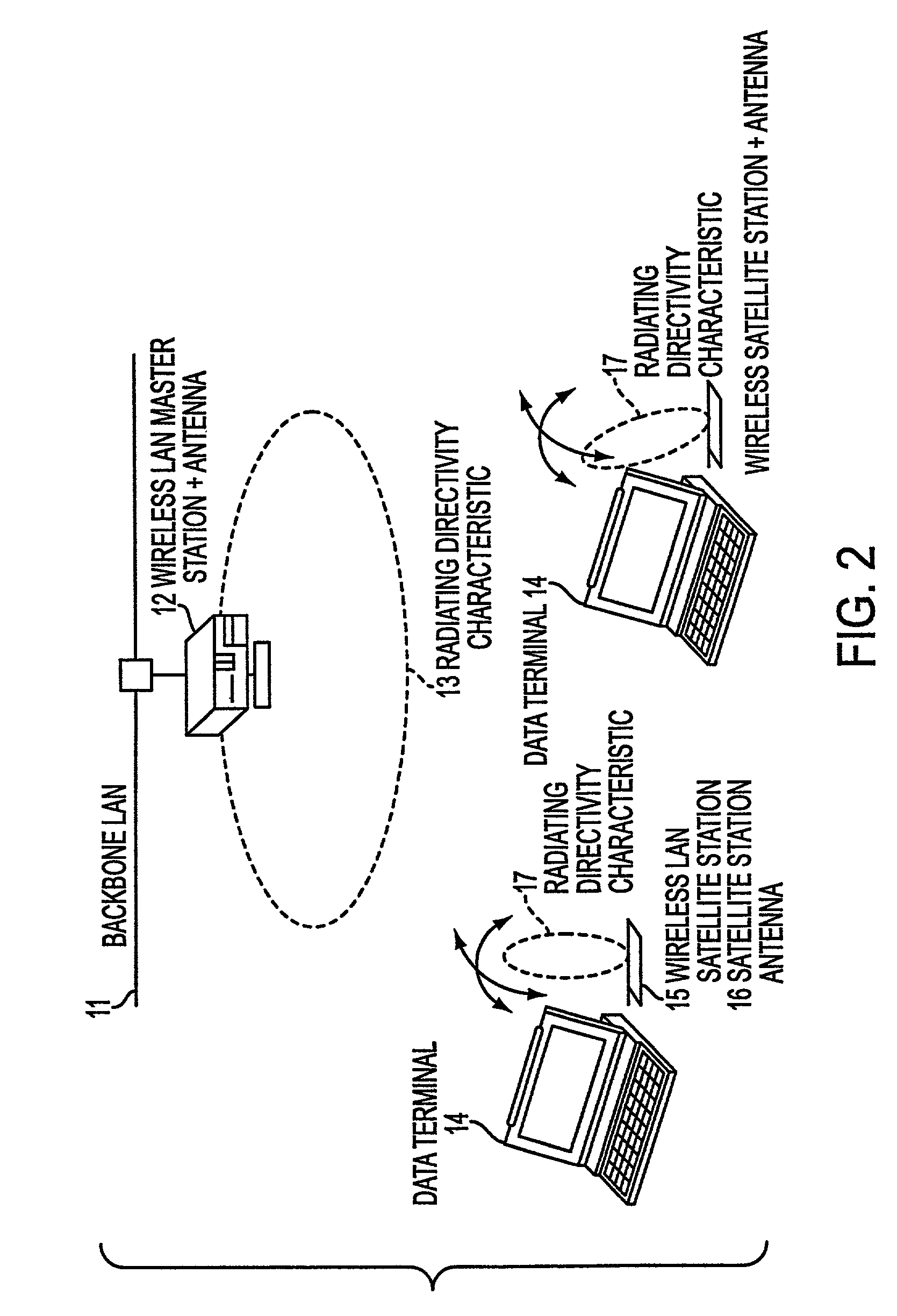
[0043]FIG. 1 is a block diagram of the principle and the configuration of the present invention. This is a block diagram of the theoretical configuration of a wireless LAN system connected to a backbone LAN and comprises a wireless master station supporting communication between satellite stations belonging to the master station and one or more wireless LAN satellite stations. The master station and satellite stations are transmitter-receivers which can communicate with each other.

[0044]As shown in FIG. 1, a satellite station 4 comprises an antenna unit 1, a control frame transmitting unit 2 and an antenna directivity characteristic control unit, whereas the master station 6 comprises a carrier wave transmitting unit 5.

[0045]When the antenna unit 1 receives electric waves from the master station, the antenna unit 1 can change the directivity characteristic of the antenna unit 1. Prior to the commencement of communication with the master station or another satellite station or when c...


PUM


Abstract

In a wireless LAN system chiefly using a millimeter wave, a satellite station is provided with an active phased planar-array antenna, the radiating directivity characteristic of which can be freely changed. When a master station receives a control frame transmitted from the satellite station prior to the commencement of normal communication, the master station transmits a carrier wave. The satellite station determines such a directivity characteristic of an antenna as to receive this carrier wave with the strongest intensity, and fixes the characteristic. Thus, an optimal communication environment can be secured. When the number of errors in a received data frame or the receiving electric field intensity received by the satellite station in normal communication is inferior to a respective predetermined threshold, the deterioration of the communication environment can be coped with by determining again. The power consumption of the master station can be reduced by making the transmitting power of a carrier wave for determining less than the transmitting power at the time of normal communication.

Description

CROSS-REFERENCE TO RELATED APPLICATIONS[0001]This application is a Divisional of application Ser. No. 09 / 040,426, filed Mar. 18, 1998, now pending.BACKGROUND OF THE INVENTION[0002]1. Field of the Invention[0003]The present invention relates to a local area network (LAN), more specifically to the optimization of communication quality for realizing an optimal communication environment between a wireless LAN satellite station and a master station in a wireless LAN system mainly using an electromagnetic wave in a millimeter wave range.[0004]2. Description of the Related Art[0005]These days a LAN has become popular and the amount of data handled on a LAN has been also increasing. On the other hand, data terminals including a personal computer have been improved in communicating functions, and have been miniaturized. Under these circumstances, the need for data communication in a mobile environment is advocated, and attention is being paid to a wireless LAN system.[0006]So far an electrom...

Claims


Application Information

Patent Timeline
IPC IPC(8): H04Q7/24H04J3/16H01Q3/34H01Q3/26H04L12/28H04W28/04H04W76/02H04W84/06H04W84/12
CPCH01Q3/26H04W28/04H04B17/318H04W84/06H04W84/12H04W76/02H04W76/10
Inventor KOBAYASHI, NAOFUMI
Owner FUJITSU LTD
Why Eureka
Try Eureka