Brow pad for the headband of protective headgear

a technology for protective headgear and brow pads, which is applied in the direction of protective garments, helmet covers, hats, etc., can solve the problems of removing such brow pads from the headband, causing damage to the headband itself, and becoming disengaged from the headband

a technology for protective headgear and brow pads, which is applied in the direction of protective garments, helmet covers, hats, etc., can solve the problems of removing such brow pads from the headband, causing damage to the headband itself, and becoming disengaged from the headband

US7213271B1Active Publication Date: 2007-05-08E D BULLARD

Image

  • Brow pad for the headband of protective headgear
  • Brow pad for the headband of protective headgear
  • Brow pad for the headband of protective headgear

Examples


Embodiment Construction

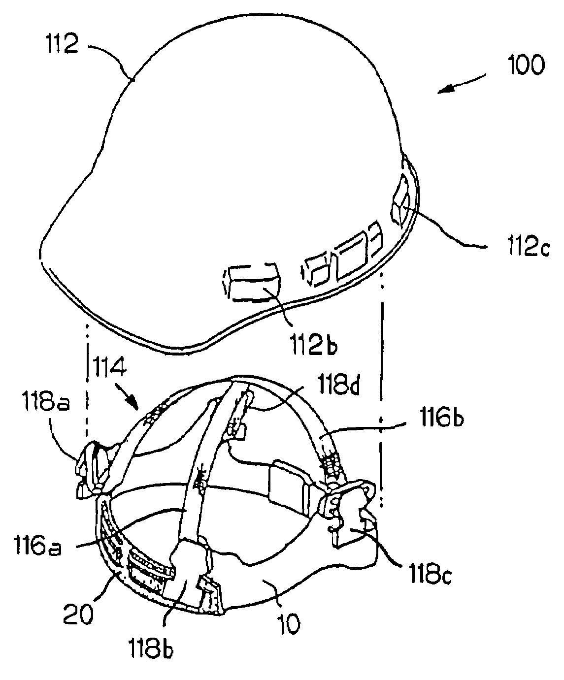
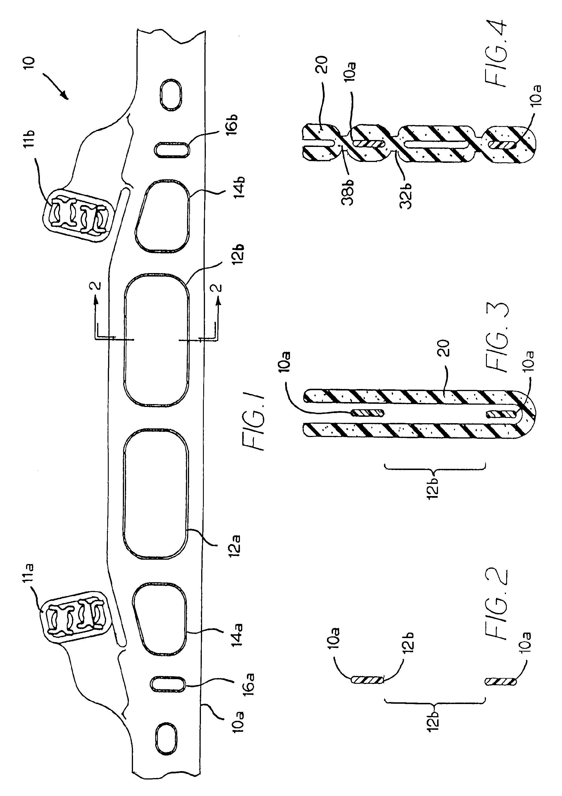
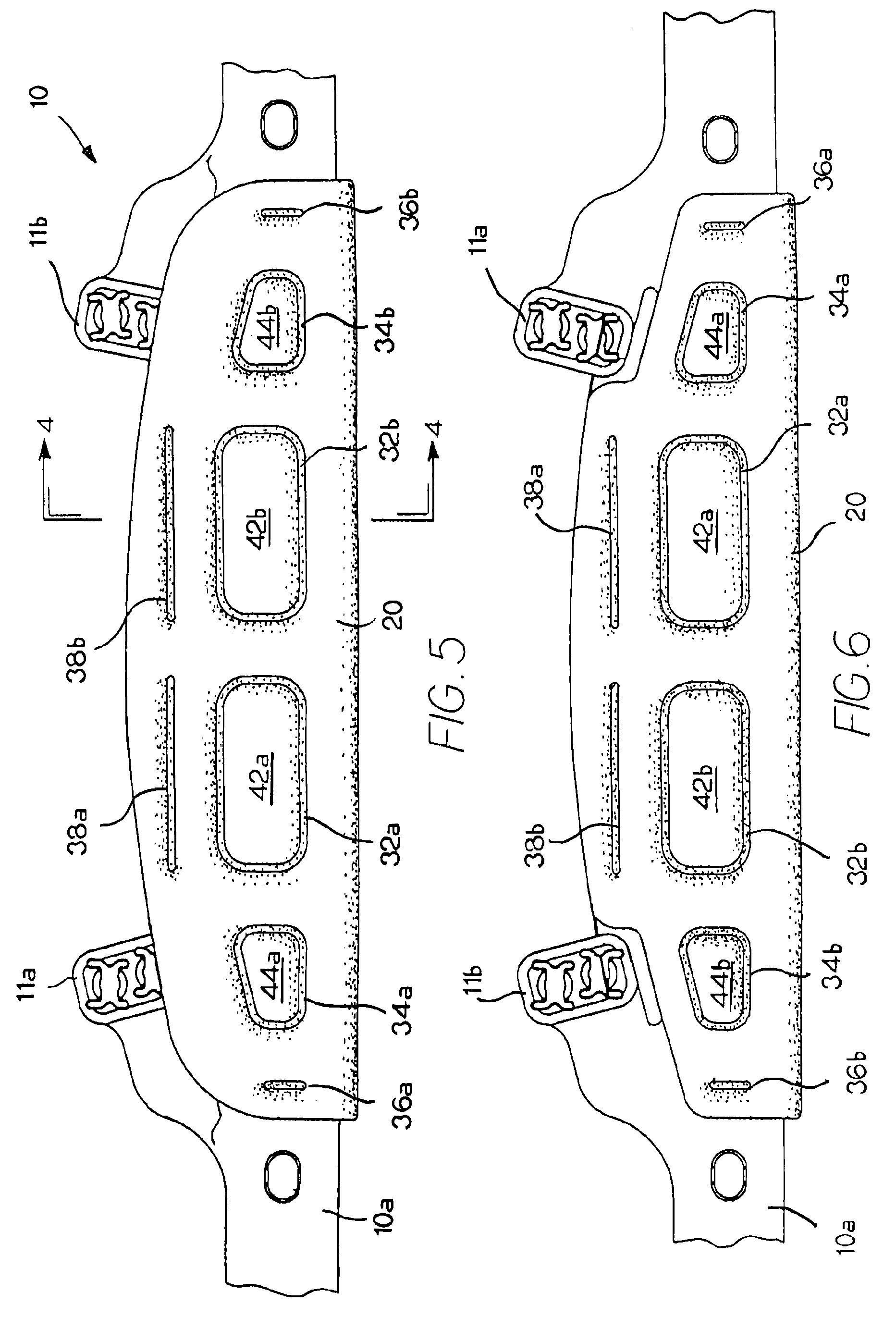
[0023]The present invention is a brow pad for the headband of a protective helmet or similar headgear, a brow pad that is ultrasonically welded or similarly joined to itself through openings defined through the headband.

[0024]FIG. 1 is a plan view of an exemplary headband 10, specifically illustrating the front portion 10a of the headband 10 that would be positioned adjacent the forehead of a wearer when the headband 10 is incorporated into an article of protective headgear, such as a hard hat, helmet, respirator hood, or faceshield. This exemplary headband 10 is designed for use with a hard hat. In this regard, the headband 10 includes a plurality of upwardly extending appendages 11a, 11b (two of which are illustrated in FIG. 1), with each such appendage 11a, 11b being used to secure the headband 10 to the suspension of the hard hat. For further details regarding the incorporation of such a headband 10 into a protective helmet, reference is made to U.S. Pat. No. 6,609,254, which is...


PUM


Abstract

A brow pad for the headband of a protective helmet or similar headgear is ultrasonically welded or similarly joined to itself through openings defined through the headband. By joining the brow pad to itself through the headband, the brow pad remains secured to the headband even after extensive usage. Furthermore, the openings defined through the headband provide some measure of ventilation and evacuation of accumulated moisture from the brow pad. Finally, by joining the brow pad to itself and through the headband, there are pockets of air that are trapped between the joined portions of the brow pad, which serve as air-filled “pillows,” providing some measure of comfort to the wearer.

Description

BACKGROUND OF THE INVENTION[0001]The present invention relates to a brow pad for the headband of a protective helmet or similar headgear.[0002]Protective helmets are commonly worn in the industrial workplace to prevent or reduce the likelihood of head injuries. The hard hat is the most common and well-recognized protective helmet. A hard hat consists of three primary components—a shell, a headband, and a suspension system—which cooperate to reduce the potential for injury by attenuating some translational energy of the force of an impact to the helmet.[0003]With respect to the construction and protection afforded by a hard hat, the American National Standards Institute (“ANSI”) promulgates minimum performance requirements for protective helmets and further classifies helmets based on their ability to reduce the forces of impact and penetration, as well as their ability to protect against high voltage electric shock. See, for example, ANSI Z89.1-1997 (R1998), American National Standa...

Claims


Application Information

Patent Timeline
08 May 2007
Publication
US7213271B1
IPC
A42B3/00
CPC
A42B3/14; A42B3/145
Inventors
BIELEFELD, ERIC