Method for automatic configuration of processing system

a processing system and automatic configuration technology, applied in the direction of program control, total factory control, instruments, etc., can solve the problems of difficult to detect early stage abnormalities and characteristic deterioration of a process, and the installation of a semiconductor-processing tool is a time-consuming procedure,

Active Publication Date: 2007-05-08
TOKYO ELECTRON LTD
View PDF19 Cites 41 Cited by
  • Summary
  • Abstract
  • Description
  • Claims
  • Application Information

AI Technical Summary

Problems solved by technology

Installation of a semiconductor-processing tool is a time consuming procedure.
In many cases, changes of process data reflecting deterioration of processing characteristics cannot be detected by simply referring to the process data displayed.
It is difficult to detect early stage abnormalities and characteristic deterioration of a process.
Inefficient monitoring of a facility can result in facility downtimes that add to the overall operational cost.

Method used


Image

  • Method for automatic configuration of processing system
  • Method for automatic configuration of processing system
  • Method for automatic configuration of processing system

Examples


Embodiment Construction

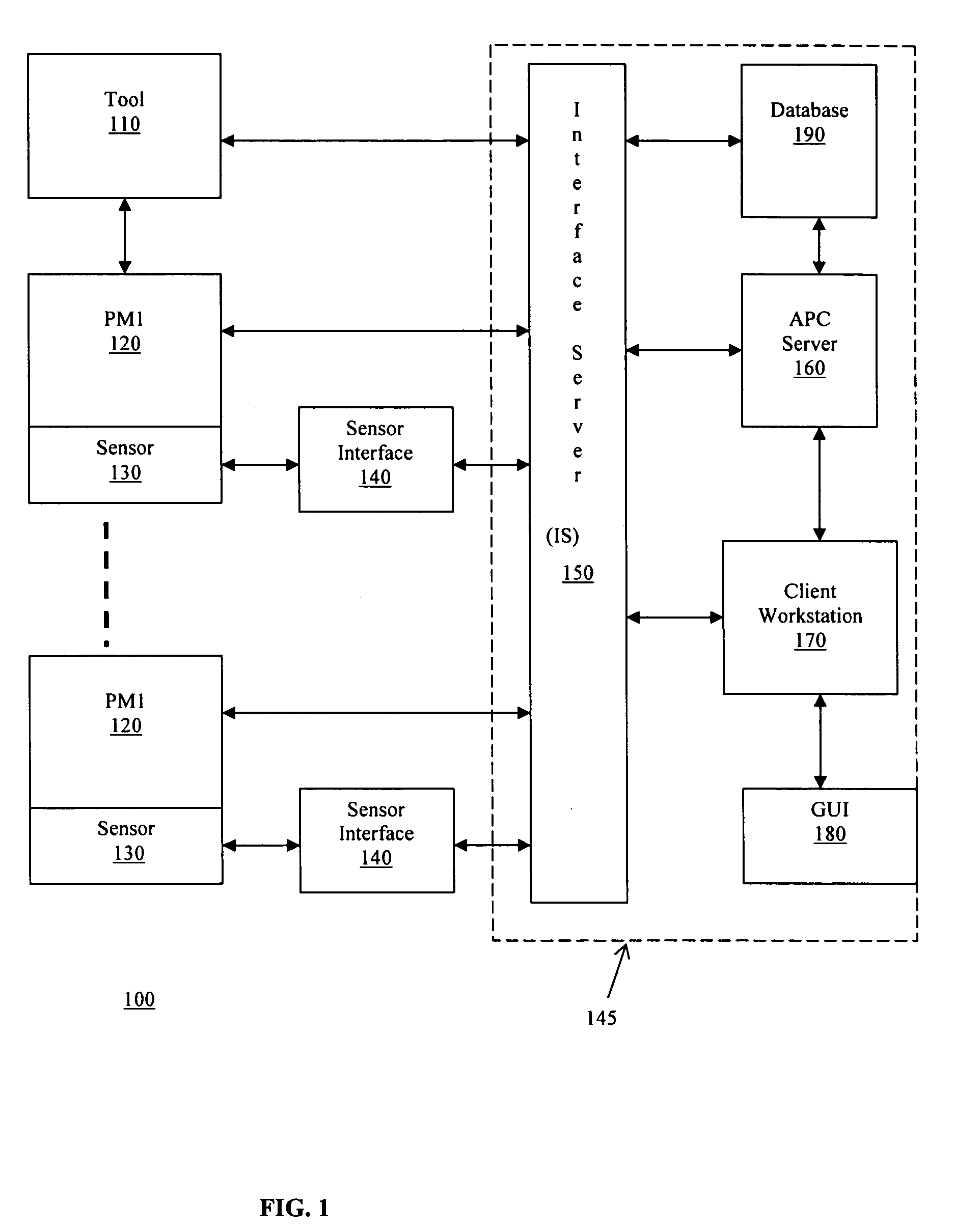
[0013]FIG. 1 shows an exemplary block diagram of an APC system in a semiconductor-manufacturing environment. In the illustrated system, semiconductor manufacturing environment 100 comprises semiconductor processing tool 110, multiple process modules 120, PM1 through PM4, sensors 130, sensor interface 140, and APC system 145. For example, sensor 130 can comprise an optical emission spectroscopy (OES) sensor for monitoring plasma conditions, a voltage / current probe (VIP) for monitoring RF signals, and / or analog sensors for measuring other process parameters such as pressure, mass flow rates, and temperature. APC system 145 can comprise interface server (IS) 150, APC server 160, client workstation 170, GUI 180, and database 190. For example, IS 150 can comprise a real-time memory database that is sometimes referred to as a “Hub”.

[0014]Additionally, for example, the APC server 145 can be coupled to an intranet, wherein the intranet further provides an Internet server (not shown) for acc...


PUM

PropertyMeasurementUnit
timeaaaaaaaaaa
processing characteristicsaaaaaaaaaa
pressureaaaaaaaaaa

Abstract

A method of automatically configuring an Advanced Process Control (APC) system for a semiconductor manufacturing environment in which an auto-configuration script is generated for executing an auto-configuration program. The auto-configuration script activates default values for input to the auto-configuration program. The auto-configuration script is executed to generate an enabled parameter file output from the auto-configuration program. The enabled parameter file identifies parameters for statistical process control (SPC) chart generation.

Description

[0001]This non-provisional application claims the benefit of U.S. Provisional Application Ser. No. 60 / 448,319, entitled “Method for automatic configuration of a processing system”, filed on Feb. 18, 2003; and U.S. Provisional Application Ser. No. 60 / 491,286, entitled “Method for automatic configuration of a processing system”, filed on Jul. 31, 2003, the contents of both of which are incorporated herein in their entirety by reference.CROSS-REFERENCE TO RELATED APPLICATIONS[0002]This application is related to U.S. Provisional application Ser. No. 60 / 414,425, entitled “Method and apparatus for the monitoring and control of a semiconductor manufacturing process”, filed on Sep. 30, 2002; U.S. Provisional application Ser. No. 60 / 393,104, entitled “Method and apparatus for automatic sensor installation”, filed on Jul. 3, 2002; U.S. Provisional application Ser. No. 60 / 393,091, entitled “Method for dynamic sensor configuration and runtime execution”, filed on Jul. 3, 2002; U.S. Provisional ...

Claims


Application Information

Patent Timeline
Patent Type & Authority Patents(United States)
IPC IPC(8): G01N19/00G05B19/418G06F19/00
CPCG05B19/41845G05B19/41865G05B2219/31334G05B2219/32191G05B2219/45031Y02P90/02Y02P90/80G05B19/4093
Inventor HARADA, SATOSHIHUME, III, EDWARD C.WILLIS, JAMES ECHAMNESS, KEVIN ANDREWLAM, HIEU AYUE, HONGYUFATKE, DAVID
Owner TOKYO ELECTRON LTD
Why Eureka
Try Eureka