Adjustable two-way valve device for a combustion engine

a two-way valve, adjustable technology, applied in the direction of engine operation, non-fuel substance addition to fuel, exhaust gas recirculation, etc., can solve the problems of inability to continuously adjust, inconvenient, and the valve cannot be used as a two-way valve device, so as to reduce assembly and production costs, cost and weight advantages, and reduce the size of the entire two-way valve devi

Inactive Publication Date: 2007-05-08
PIERBURG GMBH & CO KG NEUSS
View PDF11 Cites 17 Cited by
  • Summary
  • Abstract
  • Description
  • Claims
  • Application Information

AI Technical Summary

Benefits of technology

[0011]It is therefore the object of the invention to create an adjustable two-way valve device in which two mass flows are continuously adjustable independently of one another, whereby the number of components and thus the cost of assembly and production, as well as the size of the entire two-way valve device, are to be reduced. In addition, as far as possible only one individual valve element should be needed. As a result, cost and weight advantages are achieved. Usability in the field of exhaust gas recirculation is maintained via a high insensitivity to soiling.
[0012]A preferred embodiment of the invention is an adjustable two-way valve device for a combustion engine, comprising: a first outlet or inlet channel; a second outlet or inlet channel; a valve plate having a first passage opening of the first outlet or inlet channel and a second passage opening of the second outlet or inlet channel; a third outlet or inlet channel; and a rotary valve element having at least one control opening corresponding to one or both of the passage openings of the first and second outlet or inlet channels; wherein the valve element is disposed to controllably open or close fluid connections between the third outlet or inlet channel and one or both of the first and / or the second outlet or inlet channels, so that the openings corresponding to the first outlet or inlet channel and the second outlet or inlet channel are made independently of one another or dependent on one another. Through such an embodiment it is possible to ensure continuous adjustability with a single valve element. The construction of the two-way valve device is extremely simple and space-saving. Thus, cost and weight advantages can be achieved.
[0015]In a preferred form of embodiment a first said control opening of said valve element extends in a circumferential direction over an angular area α essentially equal to an angular area spanned by central axes of said two passage openings running through a central point of said valve plate; a second said control opening of said valve element extends in a circumferential direction over an angular area β essentially equal to an angular area made by connecting two outer, furthest-apart edges of said two passage openings with a central point of said valve plate; and said valve element features two essentially equally large closed surfaces between said two control openings. In such an embodiment all the advantages described above are realized by means of a single valve element. Both a complete closure of the passage openings is possible as well as a change of the mass flow at constant temperature. Moreover a mass flow adjustment depending on a temperature adjustment is possible and a temperature adjustment at constant mass flow.
[0016]In a preferred form of embodiment said two passage openings of said valve plate extend in a circumferential direction over an angular area of 45°, said angular area α is 50°, said first control opening extends over an angular area α of 50°; said second control opening extends over an angular area β of 95°; and said two closed faces said valve disk extend respectively over an angular area γ of 107.5°. With such an embodiment adequately large mass flows can be realized in spite of the realization of the above-described functions, and a small size and good strength are achieved.
[0017]Preferably said passage openings comprise valve seats disposed to serve as scrape edges facing said valve disk and surrounding respective ends of said first and second outlet or inlet channels. Such scrape edges as valve seats have the advantage that for example when used in the field of exhaust gas recirculation in spite of the temperatures and possibly present rust particles, these contaminants are scraped off by the scrape edges and by the rotating of valve disk and valve plate relative to one another, so that the valve is not sensitive to soiling.
[0019]Thus a two-way valve device is created that with only one valve element combines a large number of adjustment functions, is insensitive to soiling, and features a high service life with small size.

Problems solved by technology

As a rule these are not continuously adjustable and for example are not suitable for regulated exhaust gas recirculation via a cooler or a bypass, since the movable armature situated in the stream would be too sensitive to soiling and sufficient flow cross-sections are not ensured in such valves.
However, such a valve cannot be used as a two-way valve device, since the outlet channels cannot be opened or closed individually, but always jointly and simultaneously, so that an identical mass flow is made available to each outlet channel.
In the known embodiments of two-way valve devices, the disadvantages of high cost and a large number of components are evident.
It is very expensive to embody the control units with two meshing valve rods.
Moreover there is a high sensitivity to soiling in embodiments with springs arranged in the channel and valve elements sliding on the valve rod, since rust deposits may form on the valve rod, as a result of which problem-free functioning is no longer ensured.
In addition, the expense of production and assembly is very high due to the large number of components.

Method used


Image

  • Adjustable two-way valve device for a combustion engine
  • Adjustable two-way valve device for a combustion engine
  • Adjustable two-way valve device for a combustion engine

Examples


Embodiment Construction

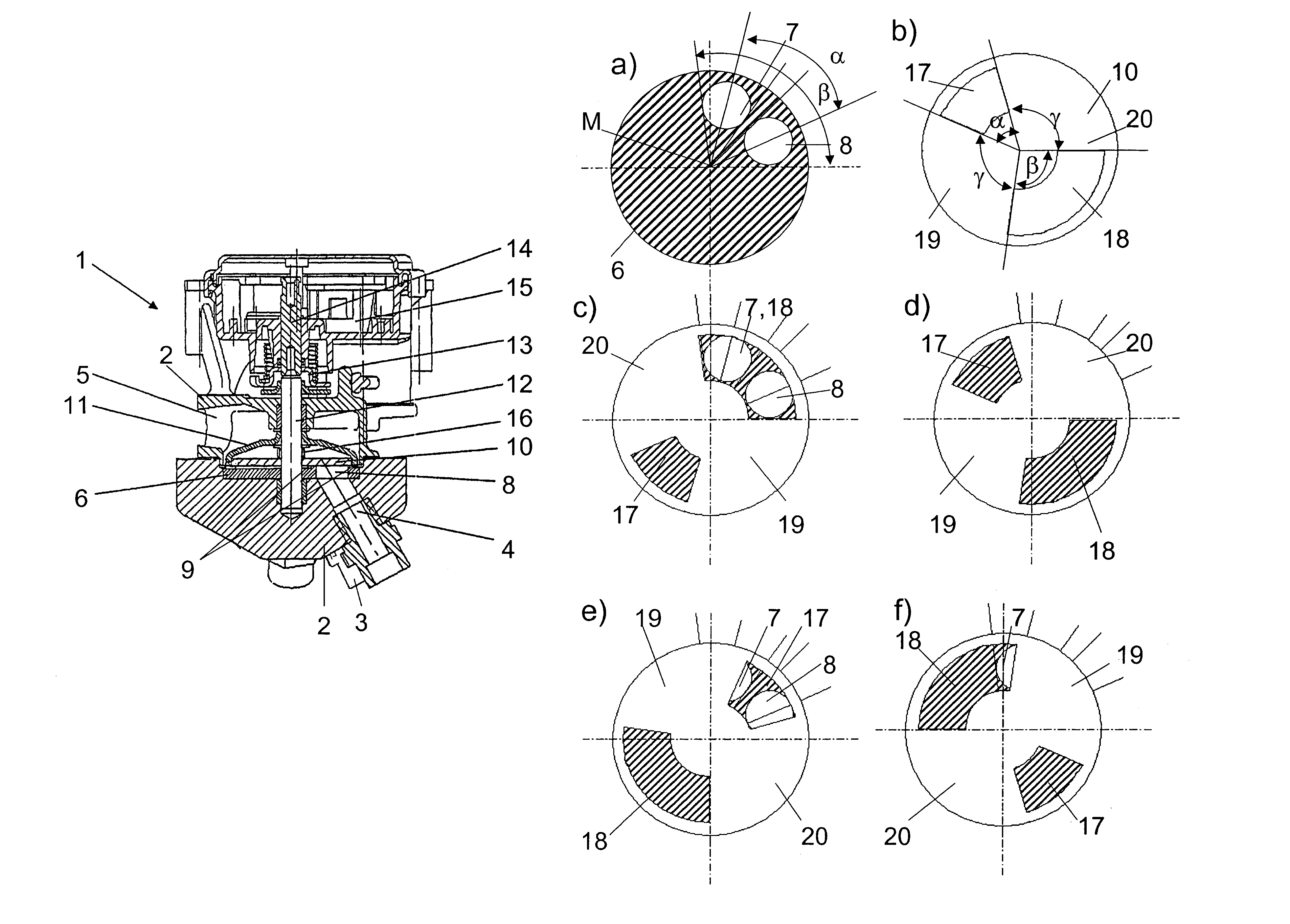
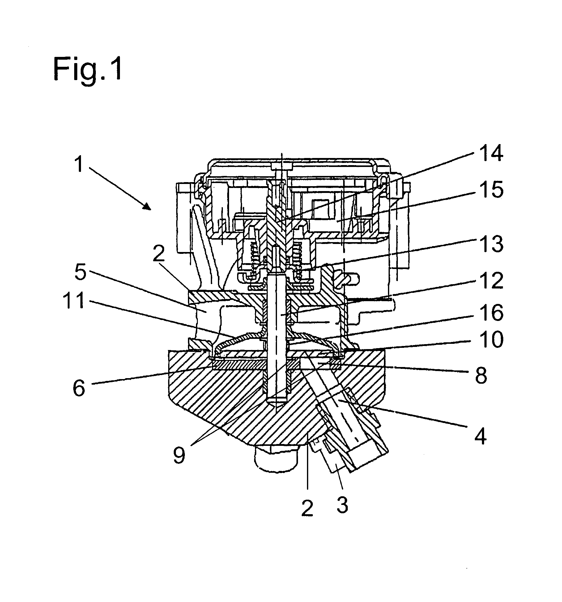
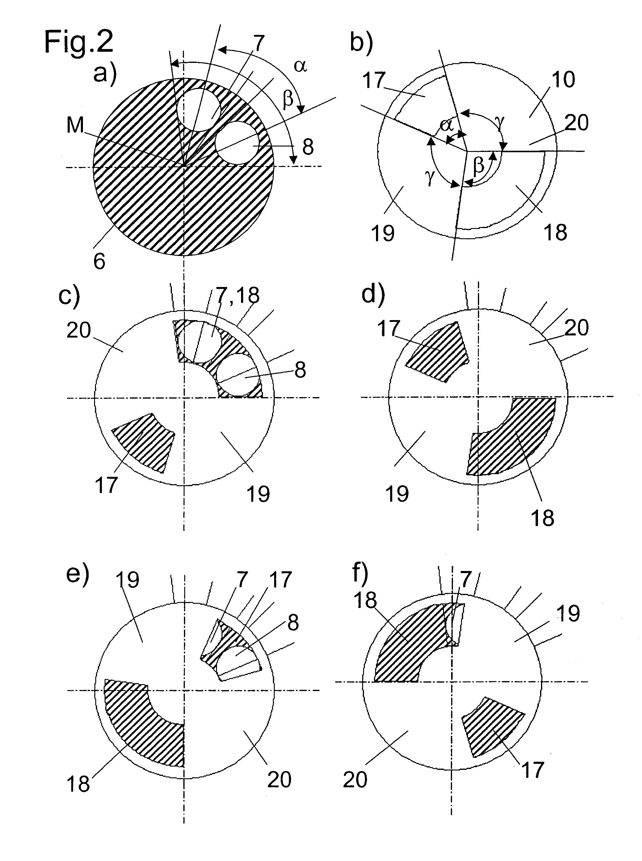
[0023]The two-way valve device 1 shown in FIG. 1 is embodied as a rotary valve and features a multi-part housing 2 in which three channels 3, 4, 5 are arranged. The first channel 3 can be arranged, for example, downstream of an exhaust gas cooler and thus can serve as an inlet channel for the rotary valve 1. The second channel 4 can be connected to a bypass channel bypassing an exhaust gas cooler and can likewise serve as an inlet channel. In this case, the channel 5 would be connected to an exhaust gas channel leading to an air intake channel system. However, as an alternative, it is also conceivable to use the third channel 5 as an inlet channel and to connect this to an exhaust manifold. The two channels 3, 4 serving as an outlet channel would then accordingly form the connections to an exhaust gas cooler and to a bypass channel bypassing the exhaust gas cooler. The respective ends of the channels 3 and 4 are formed by a valve plate 6 that features passage openings 7, 8 correspon...


PUM


Abstract

An adjustable two-way valve device is described that is embodied as a rotary valve. According to the invention the use of the rotary valve as a two-way valve is achieved by the skillful arrangement of passage openings of a valve plate with respect to control openings of a valve element. Thus it is possible to control mass or mixed flows independently of or dependent on one another with only one valve element. In particular a use in the field of exhaust gas recirculation with a bypass line and an exhaust gas cooler is advantageous, since mixed flows and thus temperatures can be run.

Description

[0001]This application claims priority on DE 10 2004 040 221.3 filed Aug. 19, 2004, the entire disclosure of which is incorporated herein by reference.BACKGROUND OF THE INVENTION[0002]1. Field of the Invention[0003]The invention relates to an adjustable two-way valve device for a combustion engine with a housing in which a first and a second outlet or inlet channel, a third outlet or inlet channel, and at least one valve element are arranged, whereby the at least one valve element is movable via a control unit such that a fluid connection can be produced at will between the first or the second outlet or inlet channel and the third outlet or inlet channel.[0004]2. Background Art[0005]Such two-way valve devices are known for example as combined exhaust gas recirculation and bypass valve devices in which two valve elements are activated translationally via a continuously adjustable control unit in order to reduce the emissions of a combustion engine in that in the warm-up phase the exh...

Claims


Application Information

Patent Timeline
Patent Type & Authority Patents(United States)
IPC IPC(8): F02M25/07F02B47/08F16K31/02F16K5/00
CPCF02M25/0729F02M25/0773F02M25/0793F02M25/0701Y02T10/121F02M26/26F02M26/50F02M26/54F02M26/70
Inventor RUTTEN, PETER
Owner PIERBURG GMBH & CO KG NEUSS
Why Eureka
Try Eureka