Object storage device and climate-controlled cabinet

a storage device and object technology, applied in mechanical control devices, loading/unloading, load-engaging elements, etc., can solve the problem of the ratio of the number of cassette storage spaces to the required surface area, and achieve the effect of preventing heat/cold bridges, reducing the risk of contamination, and cleaning or replacement quickly and simply

Active Publication Date: 2007-05-08
THERMO ELECTRONICS LED GMBH
View PDF18 Cites 20 Cited by
  • Summary
  • Abstract
  • Description
  • Claims
  • Application Information

AI Technical Summary

Benefits of technology

[0017]With regard to decreasing the risk of contamination it is furthermore highly advantageous that drive devices be arranged at the end of the first and second torque shaft, as well as of the longitudinal threaded spindle, and that the drive devices be arranged outside of an internal housing space, where the first and second torque shafts are led through the wall of an internal housing space.
[0018]The X-Y track system with the hoisting unit and the transport platform can be completely removed from the internal space for cleaning or replacement quickly and simply since it is arranged on a bottom frame with four corner braces, and it is attached in a removable manner to the upper end areas of the corner braces.
[0019]In this context, it is advantageous, for the purpose of preventing heat / cold bridges, that the ends of the first and second torque shaft and of the threaded spindle, which are led out of the internal space, are provided with a temperature-insulating intermediate part in the outlet area.

Problems solved by technology

As a result of the system, the ratio of the number of cassette storage spaces to the required surface area worsens as the number of cassette storage spaces increases.
In addition, the drive devices for the hoisting unit and the tilting mechanism are arranged in the work space which can be disadvantageous with regard to the cleaning of the work space and its disinfection.

Method used


Image

  • Object storage device and climate-controlled cabinet
  • Object storage device and climate-controlled cabinet
  • Object storage device and climate-controlled cabinet

Examples


Embodiment Construction

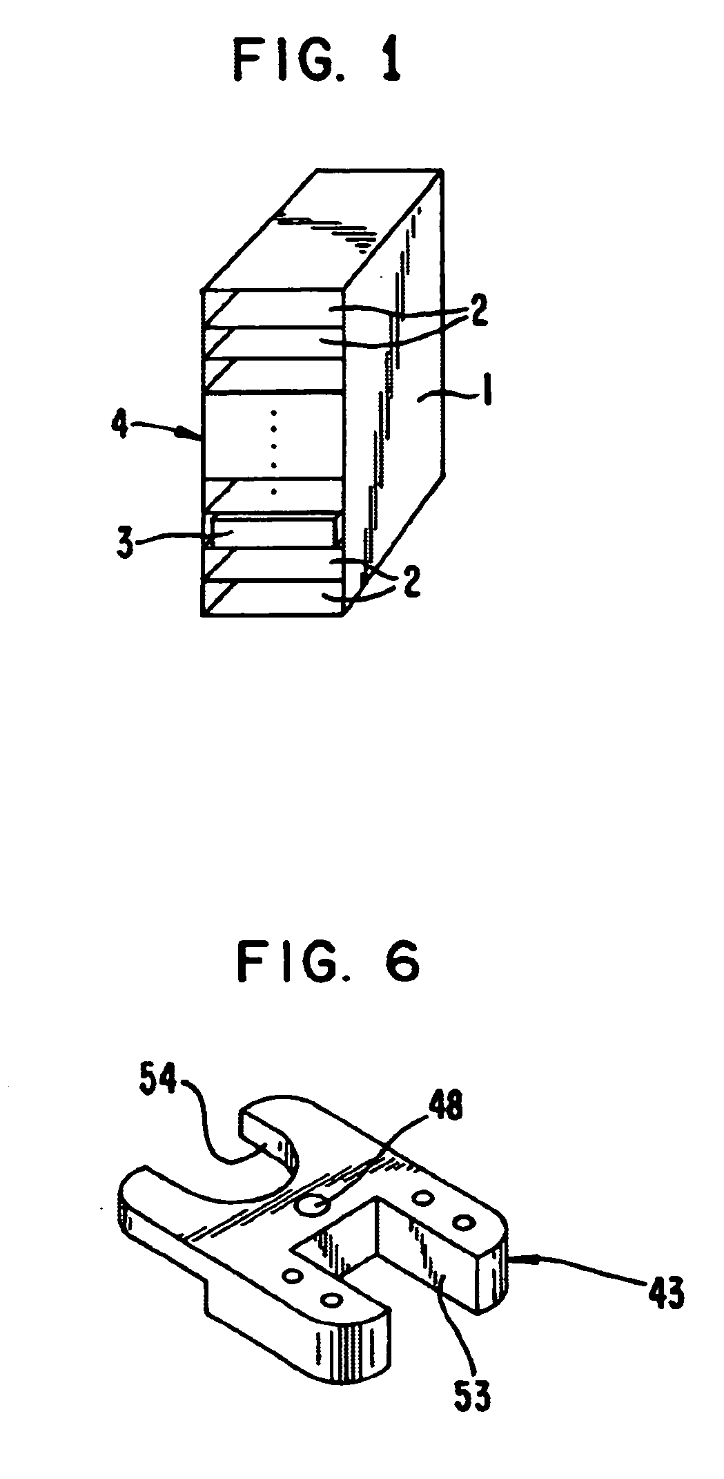
[0035]FIG. 1 depicts a cassette 1 with a multitude of shelf-like storage slots 2, which are arranged one on top of another, each for an object 3, for example, a microtiter plate. The storage slots 2 can be accessed from a front side 4 in such a way that an object 3 can be deposited in a storage slot 2 or removed from a storage slot 2.

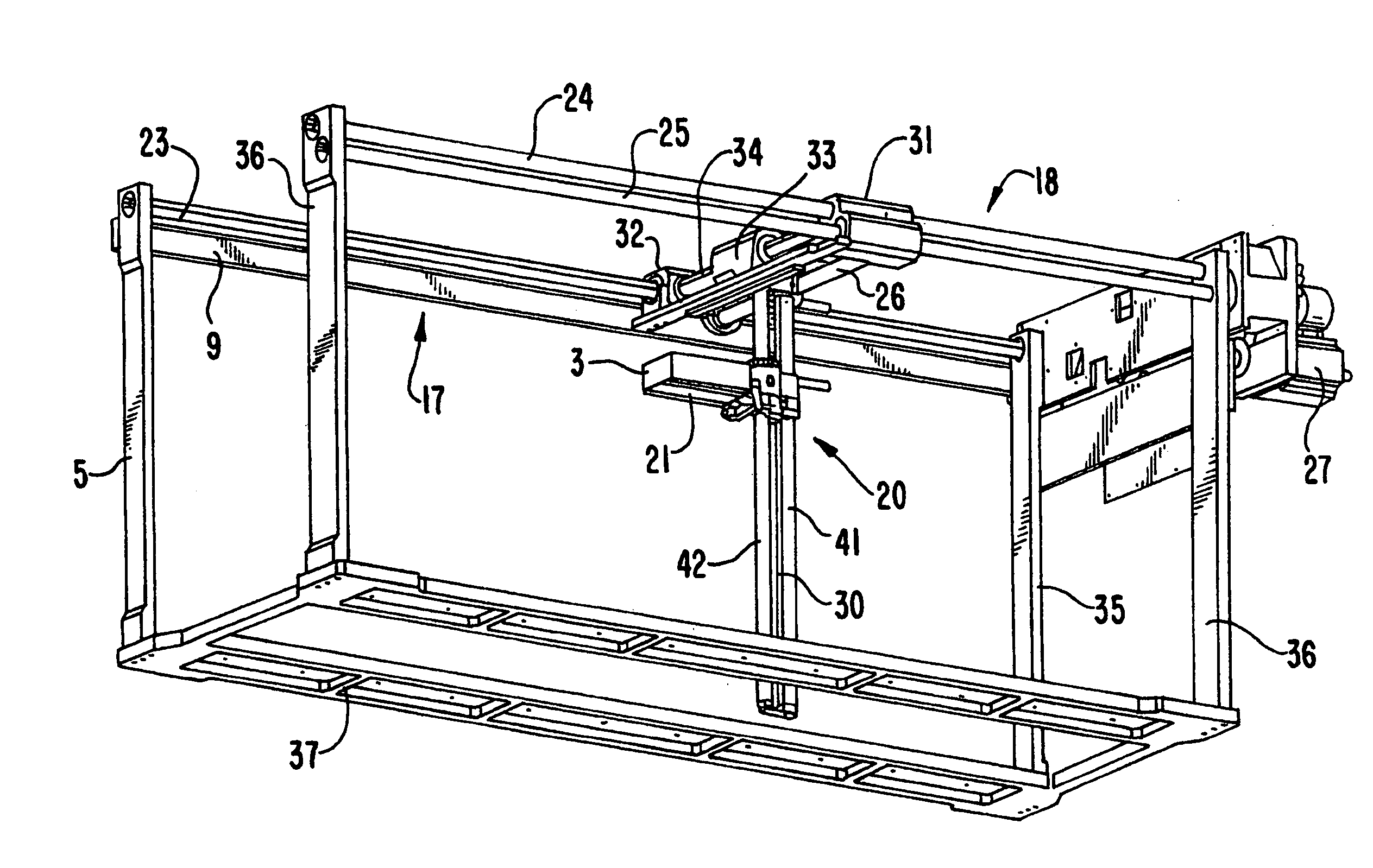
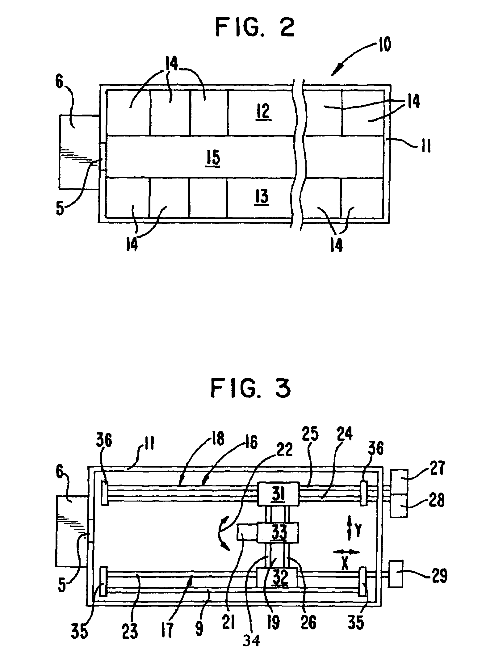
[0036]According to FIG. 2, the plan of an object storage device is represented using the example of a climatic chamber 10, which is surrounded by an internal wall 11. In the interior of the climatic chamber 10, two parallel rows 12, 13 of storage spaces 14 for cassettes 1 (FIG. 1) are arranged along a passage 15. Each storage space 14 can receive a cassette 1. The accessible front sides 4 of the cassettes 1 are all turned toward the passage 15, so that all the storage slots 2 are accessible from the passage 15 to a transport platform 21 (FIG. 3). At the end of the passage 15, a closable opening 5 leading to a transfer station 6 is located in the interna...


PUM

PropertyMeasurementUnit
tilt angleaaaaaaaaaa
heightaaaaaaaaaa
torqueaaaaaaaaaa

Abstract

The invention pertains to an object storage device with at least two storage spaces for stackers as well as a horizontally tiltable transport platform whose height can be displaced by a hoisting unit. The hoisting unit is arranged at a base point, which can be moved horizontally over an X-Y track system, which has the advantage that, in principle, any number of stackers can be arranged in two parallel rows next to each other. It is preferred that the hoisting unit be suspended from the X-Y track system with the free end hanging down.

Description

FIELD OF THE INVENTION[0001]The invention pertains to an object storage device with at least two storage spaces for cassettes as well as a transport unit for an object which presents a hoisting unit and a horizontally tiltable transport platform. The invention, furthermore, pertains to a climate-controlled cabinet with this object storage device.BACKGROUND OF THE INVENTION[0002]An object storage device and a climate-controlled cabinet of this type are known from WO 9 8 / 05753. Typically they are used in the laboratory, particularly in the fields known as the life sciences and materials science. In principle, a large variety of objects can be accommodated in such an object storage device. Standardized objects in this connection are, in particular, microtiter plate (MTP), which are deposited one on top of another in stationary or transportable cassettes (stackers) with a predetermined number of storage surfaces. In an object storage device, several storage spaces for these cassettes ar...

Claims


Application Information

Patent Timeline
Patent Type & Authority Patents(United States)
IPC IPC(8): G05G11/00B65G1/00B65G1/04B65G1/137G01N35/00G01N35/02G01N35/04
CPCB65G1/0407B65G1/1375G01N35/0099G01N35/028G01N2035/042
Inventor MELCHING, ACHIM
Owner THERMO ELECTRONICS LED GMBH
Why Eureka
Try Eureka