Apparatus and method for processing fluids

a technology of apparatus and fluids, applied in the field of fluid mixing, can solve the problems of affecting the processing efficiency of fluids, requiring energy, and costing money, and achieve the effects of increasing the ability of fluid particles, increasing the pressure of process fluids, and increasing the kinetic energy of fluid particles

Inactive Publication Date: 2007-05-08
PARRENT KENNETH GAYLORD
View PDF2 Cites 5 Cited by
  • Summary
  • Abstract
  • Description
  • Claims
  • Application Information

AI Technical Summary

Benefits of technology

[0013]Each stage in said multi-stage apparatus increases pressure on said process fluid. Said pressure increase permits reduction of the inside diameter of the succeeding nozzles, thereby causing an increase in fluid velocity as previously explained which, in turn increases said kinetic energy of said fluid particles, which in turn increases the ability of said fluid particles to do more work in providing greater sheer, improved blending, finer particle-size reduction, more thorough homogenization, more consistent particle-size reduction, finer deagglomeration and the like.
[0014]The combined beneficial effects of high-fluid velocities, very-high-level kinetic energy, high-sheer-energy, confined turbulence and multi-stage fluid processing are integrated in said invention to provide a more efficient, more versatile method and apparatus for fluids processing than hitherto available.

Problems solved by technology

Conventional fluid processing such as blending, emulsifying, deagglomerating, and homogenizing operations and the like often disregard conventional wisdom that molecules vary greatly in size, physical complexity, electrical or magnetic characteristics, and the like, thereby frequently making their processing difficult.
Also many substances have a phobia for other substances, yet their intimate combination may be desirable although very difficult to achieve.
Development of force requires development of pressure, which requires energy, which costs money.

Method used


Image

  • Apparatus and method for processing fluids
  • Apparatus and method for processing fluids
  • Apparatus and method for processing fluids

Examples


Embodiment Construction

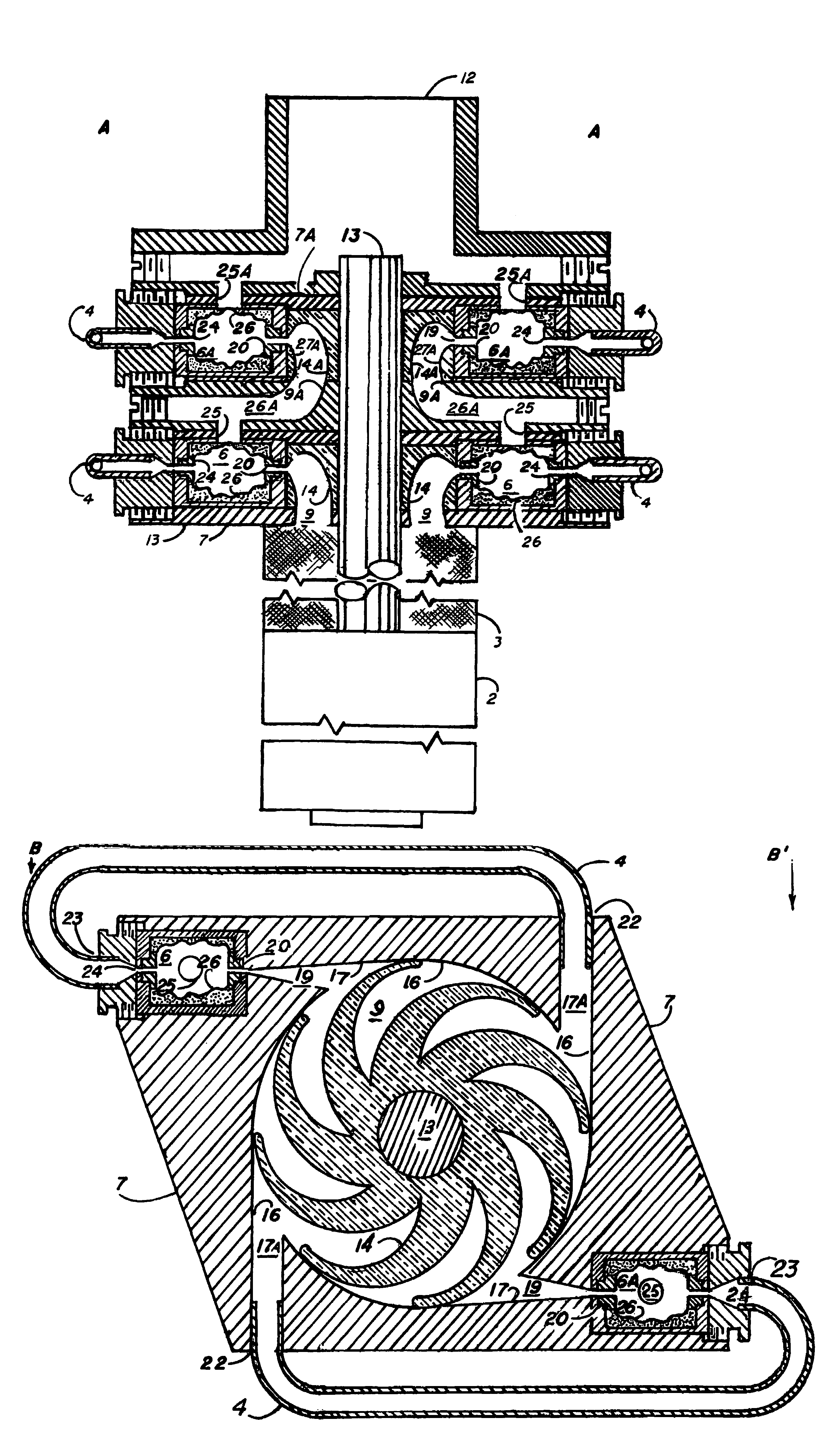
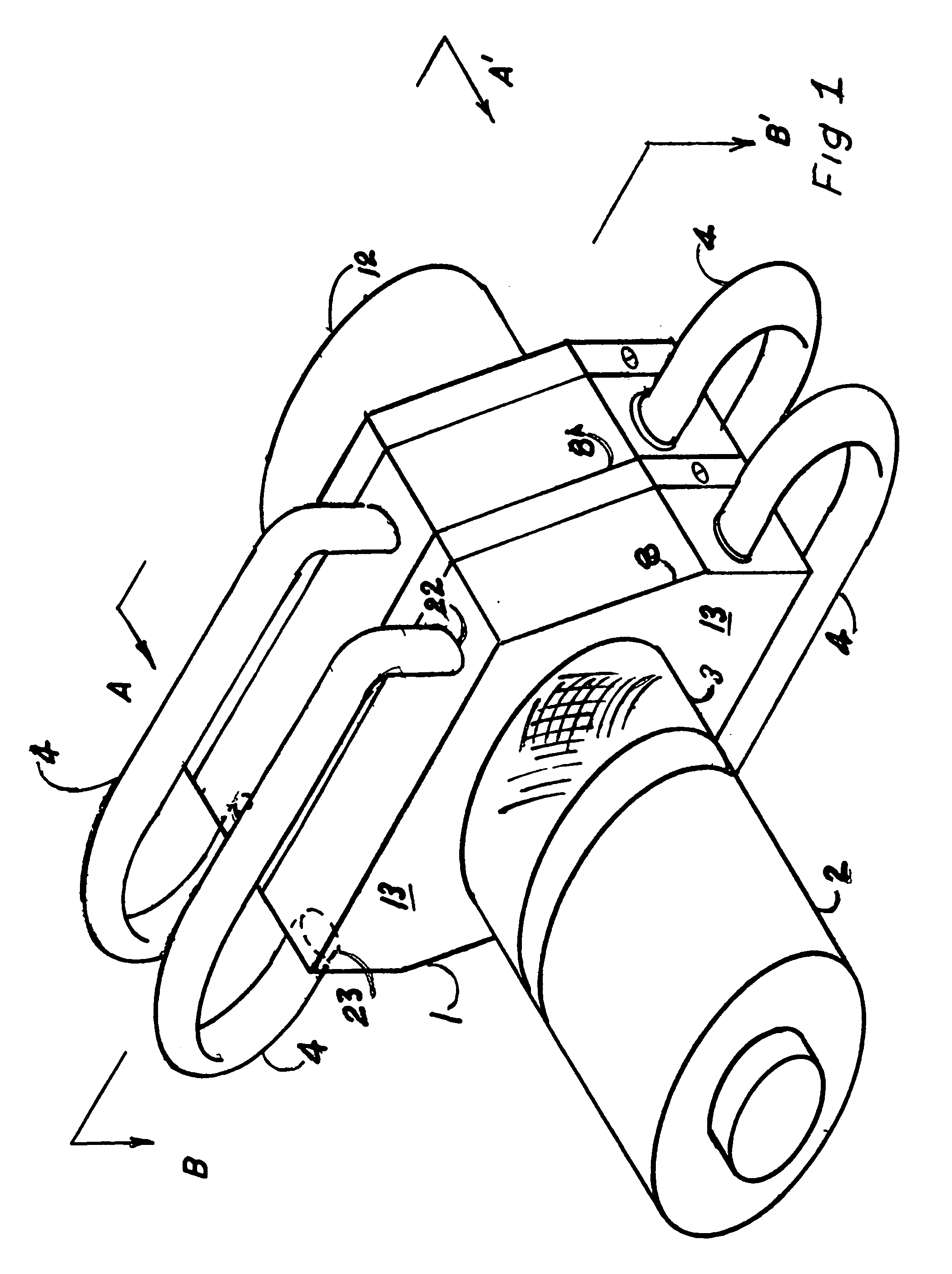
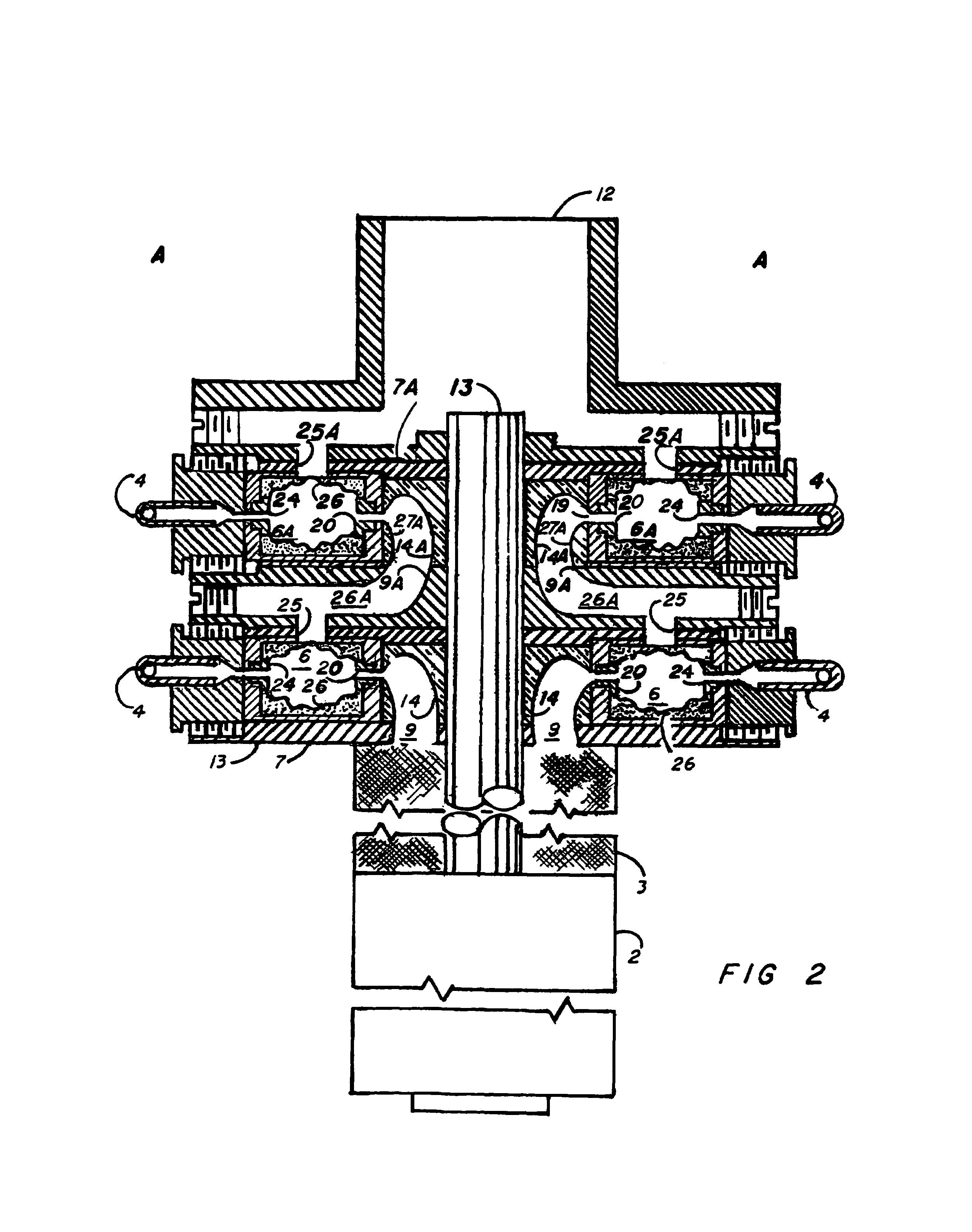
[0019]Reference is made to FIG. 1 wherein there is shown in perspective one embodiment of an apparatus in accordance with the invention generally indicated at 1. Said assembly includes a prime mover 2 such as an electric motor which provides rotary motion to the internal impellors 14&14A, FIG. 2; a screen 3 to prevent unwanted debris from entering said devise; a discharge fitting 12 and external fluid conduits 4 to conduct fluid from said impellors 14&14A to their specific Parr Chambers 6&6A, FIG. 2 located internally at position 13, FIG. 1 within said impellor housings 7&7A, FIG. 2. Although for simplicity FIG. 1 depicts only two stages 8&8A, FIG. 1 of one embodiment of an apparatus in accordance with the invention, said device may be adapted to perform more thorough fluid processing or other types of fluid processing or its capacity increased by increasing its physical dimensions and / or by increasing the number of process stages, Parr Chambers on each stage and input horsepower. S...


PUM


Abstract

An apparatus and a method for a versatile, multi-stage, centrifugal fluids-processing device adaptable to efficiently mixing, blending, emulsifying, deagglomerating or homogenizing fluids. The device comprises a centrifugal-pump-type mechanism comprising an electric motor, an intake screen, an elongate metal body, a central drive shaft extending from the motor to the discharge end of the device. Attached internally to the drive shaft is one impellor per stage, which by rotation of the motor, imparts kinetic energy to the fluid being processed. The fluid discharged from the impellors passes through separate conduits and opposing nozzles into opposite ends of a chamber having the internal shape of an oblate-spheroid with internally-ribbed ceramic walls. As the fluid streams being slightly divergent upon contact with each other they are mutually deflected at high-velocity and high turbulence to impact against the ribbed inner walls of the fluid processing chamber in directions away from the outlet from fluid processing. The orientation of the incoming fluid streams aids in providing optimum use of the fluid's kinetic energy in turbulence and high-sheer contact prior to the fluids exiting the fluid processing chamber.

Description

BACKGROUND OF THE INVENTION[0001]1. Field of the Invention[0002]This invention relates to the general field of fluids mixing, blending, emulsifying, deagglomerating, and homogenizing by virtue of its method of utilizing fluid kinetics to achieve the above stated fluid processing objectives from one basic design and is most particularly concerned with an improved apparatus for conserving and efficiently utilizing kinetic energy invested in fluids during fluids processing activities. Said kinetic energy being continuously replenished at every stage within a continuous, multi-stage fluid-processing operation.[0003]2. Description of the Prior Art[0004]It is generally required, when processing fluids or fluidized substances, to achieve an end product of specified-quality and performance that said product have a high degree of homogeneity, i.e. that the particles of the various agglomerated ingredients are significantly reduced in size and thoroughly dispersed among each other. Frequently...

Claims


Application Information

Patent Timeline
Patent Type & Authority Patents(United States)
IPC IPC(8): F04D17/12
CPCB01F5/0256B01F13/1013B01F13/1016B01F15/0201B01F15/0243F04D29/445B01F25/23B01F33/81B01F33/811B01F35/7176B01F35/71
Inventor PARRENT, KENNETH GAYLORD
Owner PARRENT KENNETH GAYLORD
Why Eureka
Try Eureka