Endoluminal stent having a matched stiffness region and/or a stiffness gradient and methods for providing stent kink resistance

a technology of kink resistance and endoluminal stent, which is applied in the field of endoluminal grafts or prostheses, can solve the problems of kinking, occlusion, or bending at the interface, and achieve the effects of minimizing kinking of an elongated stent, greater flexibility, and greater kink resistan

Inactive Publication Date: 2007-05-08
BOSTON SCI SCIMED INC
View PDF28 Cites 13 Cited by
  • Summary
  • Abstract
  • Description
  • Claims
  • Application Information

AI Technical Summary

Benefits of technology

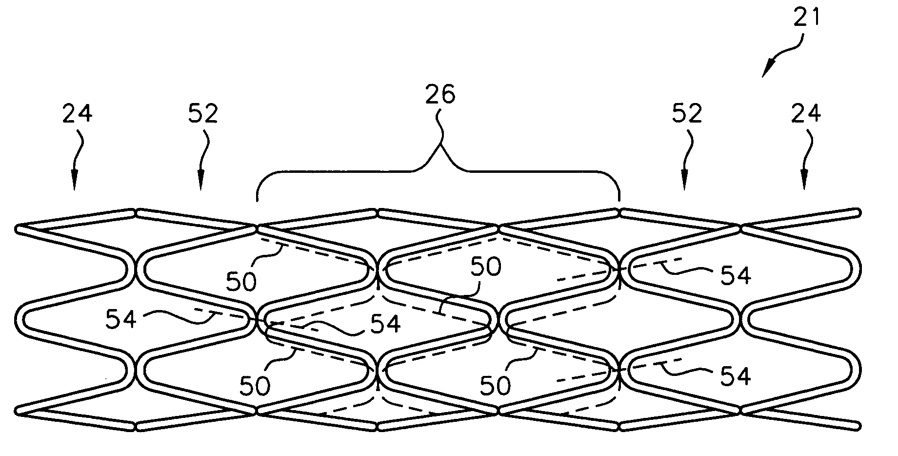
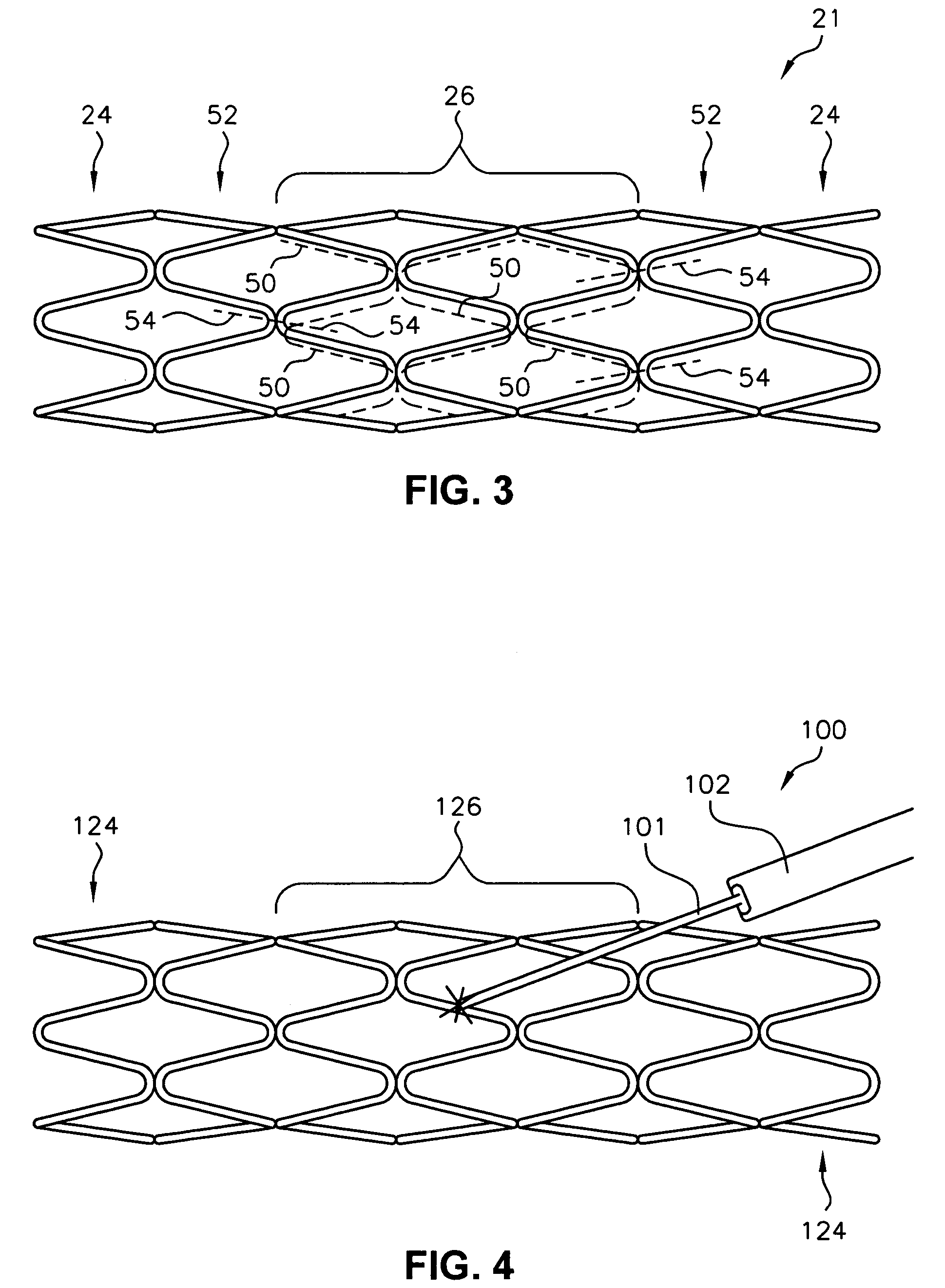
[0018]The invention also comprises a method for minimizing kinking of an elongated stent during introduction of the stent through the body lumen to a deployment location and during deployment of the stent at the deployment location. The stent has at least one stiff region with a first set of manipulation properties adjacent to at least one flexible region with a second set of manipulation properties different than the first set of manipulation properties. The second set of manipulation properties includes at least one of: greater flexibility, greater kink resistance, or less radial strength than the first set of manipulation properties. The method comprises first fabricating the stent with a transition region between the stiff region and each flexible region, the transition region having a third set of manipulation properties between the first set of manipulation properties and the second set of manipulation properties. Next, the stent is radially compressed and loaded into an introducer. Finally, the introducer is navigated through a tortuous body lumen while the transition region minimizes kinking of the stent resulting from the difference between the first set of manipulation properties and the second set of manipulation properties. The method may further comprise providing the transition region with a gradient from the first set of manipulation properties to the second set of manipulation properties.

Problems solved by technology

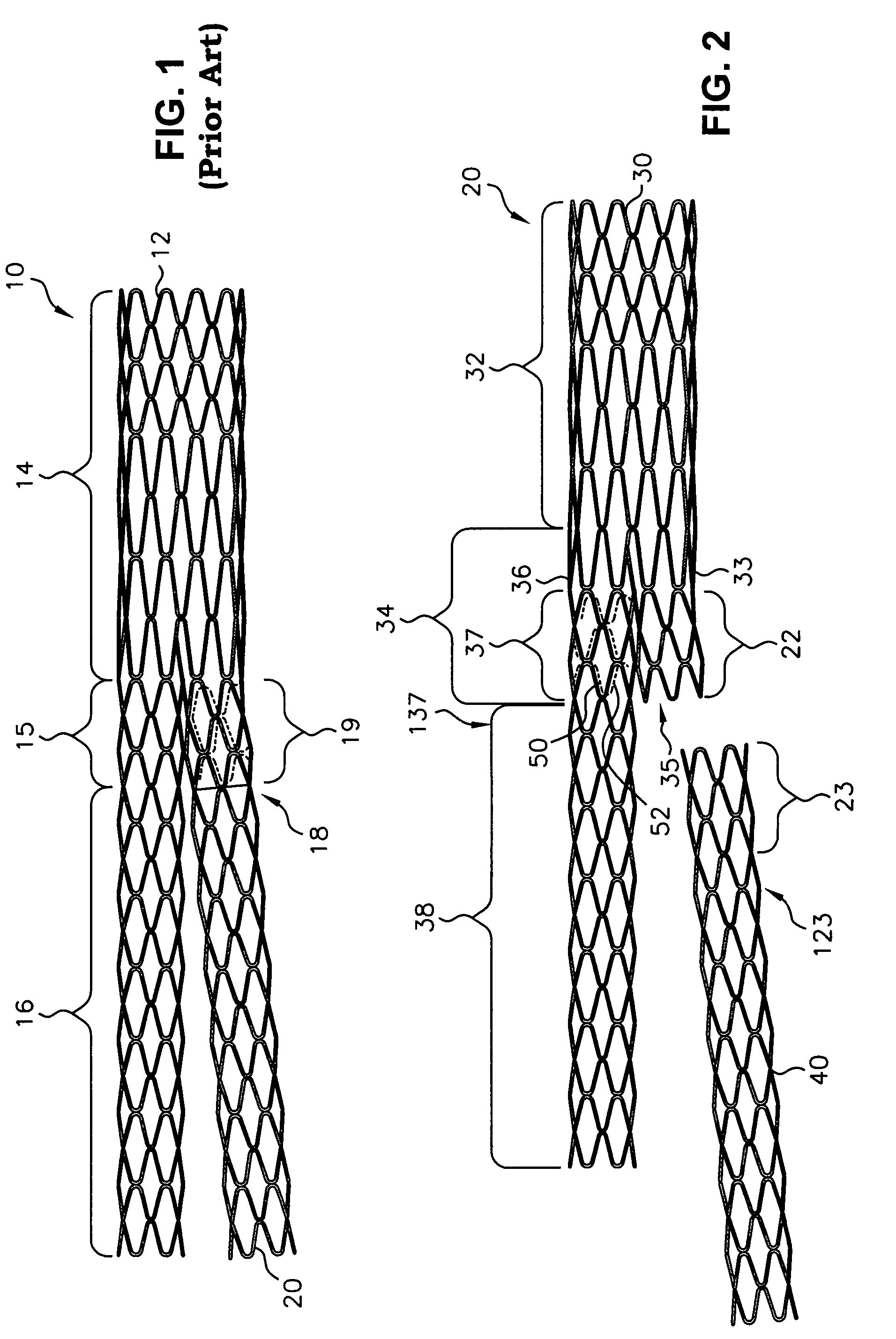
The interfaces between adjacent stent regions of different stiffness may also cause kinking, occlusion, or bending at the interface due to the drastic change in properties from one region to another.

Method used


Image

  • Endoluminal stent having a matched stiffness region and/or a stiffness gradient and methods for providing stent kink resistance
  • Endoluminal stent having a matched stiffness region and/or a stiffness gradient and methods for providing stent kink resistance
  • Endoluminal stent having a matched stiffness region and/or a stiffness gradient and methods for providing stent kink resistance

Examples


Embodiment Construction

[0035]The invention will next be illustrated with reference to the figures wherein similar numbers indicate the same elements in all figures. Such figures are intended to be illustrative rather than limiting and are included herewith to facilitate the explanation of the apparatus of the present invention.

[0036]A typical stent has a number of manipulation properties, such as stiffness or flexibility, radial strength, and kink resistance. As used herein, “flexibility” or stiffness can be described in terms of the amount of force required to deform a stent into an arc. For example, referring to the schematic representation in FIG. 11, the force f required to bend tubular stent 2000 of a particular length into a given arc having a central angle and a given arc radius, is a measure of the stent flexibility. Thus, comparing two stents of equal length with different stent architectures, the stent requiring greater force to bend it into a given arc is relatively stiffer, whereas the stent r...


PUM


Abstract

A modular elongated stent having an overlap region where two modular components fit together, the overlap region being relatively stiff as compared to another more flexible region of the stent when the stent is in an assembled configuration, the stent further comprising a mimic region that has a stiffness essentially equivalent to the stiffness of the overlap region, to provide kink resistance. A stent having such a mimic region or otherwise stiff region and a flexible region may have a transition region between the stiff and flexible regions, such as a bridging material attached to the stent, also to provide kink resistance. A stent may have relatively stiff regions and relatively flexible regions positioned to align the flexible regions with curved regions of a body lumen when deployed within the body lumen. The stiffness of the stiff, flexible, and transition regions may be controlled by attaching material to the stent, varying the cross-sectional area of the stent components, varying the metallurgical properties thereof, and / or by varying the stent architecture. Methods for providing kink resistance by controlling stent stiffness are also disclosed. A stent having regions of different metallurgical properties is also disclosed, as are methods for creating such a stent.

Description

[0001]This application is a divisional application of U.S. patent application Ser. No. 09 / 442,192, now U.S. Pat. No. 6,610,087, filed on Nov. 16, 1999.TECHNICAL FIELD[0002]This invention relates generally to endoluminal grafts or prostheses and, more specifically, to a prosthesis having regions of different stiffness.BACKGROUND OF THE INVENTION[0003]A stent is an elongated device used to support an intraluminal wall. In the case of stenosis, a stent provides an unobstructed conduit for blood in the area of the stenosis. Such a stent may also have a prosthetic graft layer of fabric or covering lining the inside or outside thereof, such a covered stent being commonly referred to in the art as an intraluminal prosthesis, an endoluminal or endovascular graft (EVG), or a stent-graft.[0004]A prosthesis may be used, for example, to treat a vascular aneurysm by removing the pressure on a weakened part of an artery so as to reduce the risk of rupture. Typically, a prosthesis is implanted in ...

Claims


Application Information

Patent Timeline
Patent Type & Authority Patents(United States)
IPC IPC(8): A61F2/06A61F2/00A61F2/86
CPCA61F2/86A61F2/91A61F2/915A61F2/064A61F2002/065A61F2220/0058A61F2002/91558A61F2250/0018A61F2250/0036A61F2220/005A61F2002/067
Inventor ZARBATANY, DAVID J.MOSKOWITZ, ARIQUIGLEY, FERGUS P.HIJLKEMA, LUKAS J.
Owner BOSTON SCI SCIMED INC
Why Eureka
Try Eureka