Percutaneous catheter and method of manufacturing tube for percutaneous catheter

a manufacturing method and technology for percutaneous catheters, applied in the field of percutaneous catheters and manufacturing methods of percutaneous catheters, can solve the problems of kink generation, complicated manufacturing steps, and deterioration of the performance of being inserted into a living body, and achieve the effects of reducing the likelihood of kink in the part provided with the side hole, reducing manufacturing costs, and increasing rigidity

Pending Publication Date: 2019-01-31
TERUMO KK
View PDF2 Cites 1 Cited by
  • Summary
  • Abstract
  • Description
  • Claims
  • Application Information

AI Technical Summary

Benefits of technology

[0008]An object of the present invention is to provide a percutaneous catheter in which a kink in a part provided with a side hole can be minimized, and a method of manufacturing a tube for a percutaneous catheter, in which productivity can be improved by forming a side hole by a comparatively easy method.
[0011]According to the percutaneous catheter having a configuration as described above, the side hole is formed in the gaps among the wires of the tubularly formed reinforcement body. Therefore, a tube portion reinforced by the wires is formed around the side hole. Thus, the increased rigidity obtained from the reinforcement body is substantially maintained in the vicinity of the side hole. Therefore, the likelihood of a kink in the part provided with the side hole can be minimized.
[0012]According to the method of manufacturing a tube for a percutaneous catheter having a configuration as described above, the side hole can be formed by utilizing the gaps among the wires of the reinforcement body. There is no need to remove the reinforcement body in order to provide the side hole, or to provide another separate member. Therefore, manufacturing becomes comparatively easy. Accordingly, a manufacturing time can be shortened, so that productivity can be improved.

Problems solved by technology

Therefore, there is concern that a kink will be generated.
Thus, the performance of being inserted into a living body deteriorates.
Therefore, a manufacturing step becomes complicated and a long manufacturing time is required, so that productivity deteriorates.
Therefore, there is concern that a kink will be generated due to the difference in rigidity between the part and other parts.

Method used


Image

  • Percutaneous catheter and method of manufacturing tube for percutaneous catheter
  • Percutaneous catheter and method of manufacturing tube for percutaneous catheter
  • Percutaneous catheter and method of manufacturing tube for percutaneous catheter

Examples


first embodiment

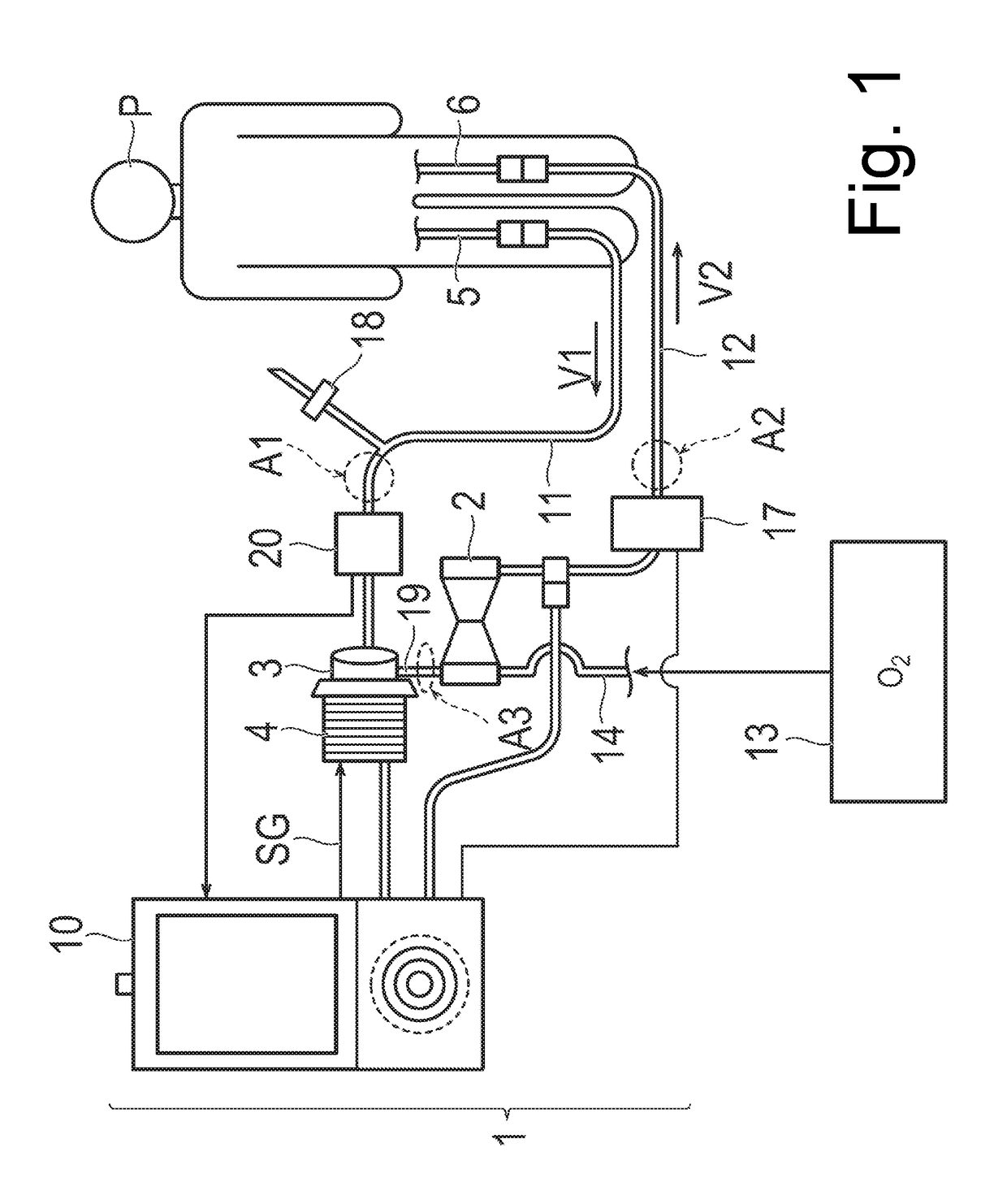
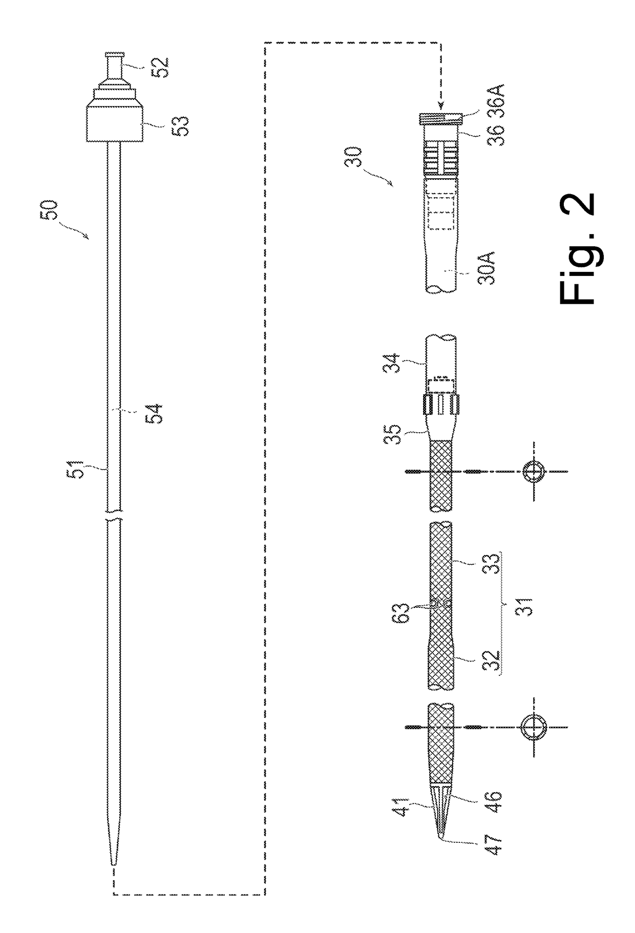
[0040]With reference to FIGS. 2 to 7, a percutaneous catheter (which will hereinafter be referred to as a “catheter”) 30 according to a first embodiment of the present invention will be described. FIGS. 2 to 7 are views describing a configuration of the catheter 30 according to the first embodiment. The catheter 30 according to the present embodiment is used as the vein side catheter (catheter for blood removing) 5 in FIG. 1.

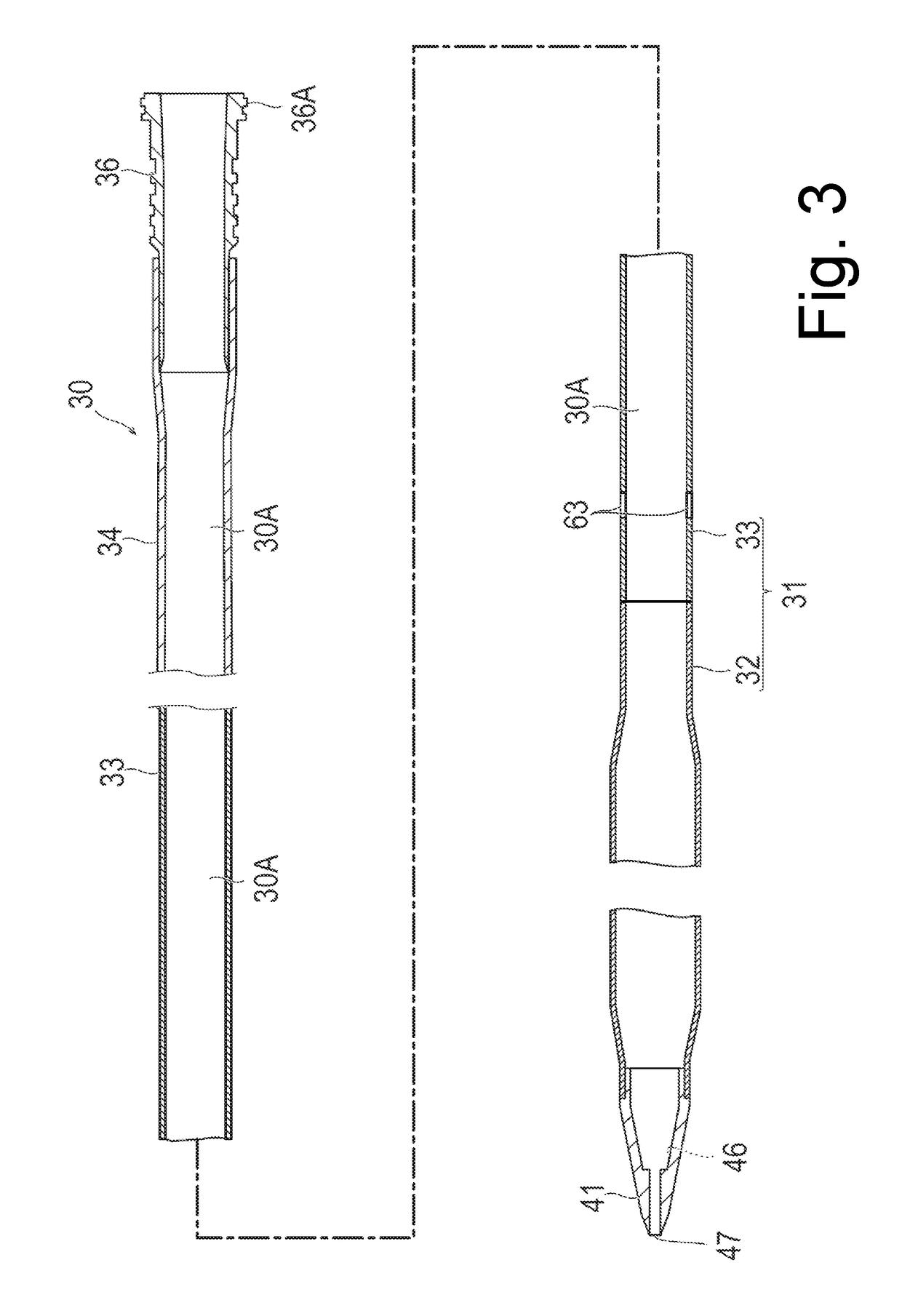
[0041]As illustrated in FIG. 2, the catheter 30 according to the present embodiment has a catheter tube (corresponding to a tube for a percutaneous catheter) 31 which includes a side hole (corresponding to a side hole on a proximal side) 63, a distal tip 41 which is disposed at a distal end of the catheter tube 31 and includes through-holes 46 and 47, a clamping tube 34 which is disposed on the proximal side of the catheter tube 31, a catheter connector 35 which connects the catheter tube 31 and the clamping tube 34 to each other, and a lock connector 36.

[0042]I...

second embodiment

[0129]With reference to FIG. 12, a percutaneous catheter (which will hereinafter be referred to as a “catheter”) 230 according to a second embodiment of the present invention will be described. FIG. 12(A) is a side view illustrating the distal side of the catheter 230, and FIG. 12(B) is a side view illustrating a situation in which the dilator 50 is inserted into the catheter 230.

[0130]Similar to the first embodiment, the catheter 230 according to the second embodiment has a catheter tube (corresponding to a tube for a percutaneous catheter) 231. The catheter tube 231 includes a first tube 232 and the second tube 33 disposed on the proximal side of the first tube 232. The first tube 232 is configured to have higher flexibility than that of the second tube 33.

[0131]As illustrated in FIG. 12(A), the catheter 230 differs from the first embodiment in further including a side hole 263 on the distal side in the first tube 232. The same reference signs are applied to portions having the sa...

third embodiment

[0137]With reference to FIGS. 13 to 15, a percutaneous catheter (which will hereinafter be referred to as a “catheter”) 60 according to the third embodiment of the present invention will be described.

[0138]A catheter 60 is a so-called double lumen catheter, which can perform both blood feeding and blood removing at the same time. Therefore, in the present embodiment, for the extracorporeal circulator 1 in FIG. 1, a technique is performed by using only the catheter 60, without using two catheters, that is, the vein side catheter (catheter for blood removing) 5 and the artery side catheter (catheter for blood feeding) 6.

[0139]As illustrated in FIG. 14, the catheter 60 according to the present embodiment differs from the catheter 30 according to the first embodiment in that a third tube 161 including a first lumen 61 communicating with a side hole (corresponding to a side hole on the proximal side) 163 for blood feeding has a double tube structure disposed in the lumen of the second tu...


PUM

PropertyMeasurementUnit
lengthaaaaaaaaaa
lengthaaaaaaaaaa
diameteraaaaaaaaaa

Abstract

A percutaneous catheter for an extracorporeal blood circulator has a tubular reinforcement body comprised of a plurality of wires braided in a reticulated manner. The braided wires include first wires wound in a first helical direction and second wires wound in a second helical direction crossing the first wires to define regular gap portions. A portion of the first and second wires are deviated from the helical directions to enlarge a selected gap portion into a first opening portion. A resin layer coats the reinforcement body and includes a second opening portion coincident with the first opening portion to form a side hole for fluid communication between an interior lumen and an exterior of the catheter. A continuous reinforcement is provided between longitudinal ends of the tubular reinforcement body including a longitudinal region of the side hole.

Description

CROSS REFERENCE TO RELATED APPLICATIONS[0001]This application is a continuation of PCT Application No. PCT / JP2017 / 009060, filed Mar. 7, 2017, based on and claiming priority to Japanese Application No. 2016-076097, filed Apr. 5, 2016, both of which are incorporated herein by reference in their entirety.BACKGROUND OF THE INVENTION[0002]The present invention relates to a percutaneous catheter and a method of manufacturing a tube for a percutaneous catheter.[0003]In the related art, treatment has been performed by a percutaneous cardiopulmonary support (PCPS) method for performing cardiopulmonary resuscitation during emergency treatment, circulation support, and respiratory support. This percutaneous cardiopulmonary support method is a method of temporarily supporting and substituting a cardiopulmonary function using an extracorporeal circulator.[0004]An extracorporeal circulator includes an extracorporeal circulation circuit constituted of a centrifugal pump, an artificial lung, a bloo...

Claims


Application Information

Patent Timeline
Patent Type & Authority Applications(United States)
IPC IPC(8): A61M25/00A61M1/16A61M1/26A61M1/36A61M39/28B29C63/24B29C63/00
CPCA61M25/005A61M25/007A61M25/003A61M25/0068A61M25/0012A61M25/0015A61M25/0045A61M1/1698A61M1/262A61M1/3626A61M1/3666A61M39/28B29C63/24B29C63/0004A61M2205/0266A61M2025/0031A61M2205/3375A61M2205/3344A61M2039/229A61M29/02B29K2705/00B29L2031/7542A61M25/00A61M25/0009A61M25/0051A61M25/0054A61M2025/0059A61M25/0102A61M2025/0046A61M1/3659A61L31/14A61M2207/00
Inventor YOKOYAMA, KENJI
Owner TERUMO KK
Why Eureka
Try Eureka