Evaporated fuel processing device

a technology of evaporation fuel and processing device, which is applied in the direction of machine/engine, combustion air/fuel air treatment, separation process, etc., can solve the problems of increasing standards, increasing the complexity of equipment necessary to meet them, and evaporative canisters not being designed to meet new requirements,

Inactive Publication Date: 2007-05-08
DELPHI TECH INC
View PDF11 Cites 15 Cited by
  • Summary
  • Abstract
  • Description
  • Claims
  • Application Information

AI Technical Summary

Benefits of technology

[0007]According to the invention, an evaporated fuel processing device is proposed, the device comprising a tank port and an atmospheric port; a first adsorbent chamber between the tank port and the atmospheric port, and a second absorbent chamber between the first adsorbent chamber and the atmospheric port, the first and second adsorbent chambers being filled with an adsorbent material. According to an important aspect of the invention, at least two elongate flow passages are arranged in parallel between the first adsorbent chamber and the second adsorbent chamber. The at least two elongate flow passages provide a better flow distribution of the vapour through the evaporated fuel processing device. Due to the longer flow passages—as compared to the short passages, i.e. via the compensator chamber, of the prior art devices—the time needed for the air / fuel vapour mixture to flow from the first adsorbent chamber to the second adsorbent chamber is increased. The vapour mixture is thereby homogenised and a better balance of vapour front reaching the second adsorbent chamber is achieved. The efficiency of the evaporated fuel processing device can hence be increased. Alternatively, the volume and / or quality of the adsorbent material can be reduced without losing on efficiency, whereby costs can be saved while maintaining the efficiency of the device.
[0008]Preferably, the elongate flow passages are substantially free from adsorbent material. The flow of air / fuel vapour mixture through the elongate flow passages is hence not unduly restricted. The flow distribution, and hence the efficiency of the device, is increased.
[0010]Preferably, a first elongate flow passage has a first cross-section and a second elongate flow passage has a second cross-section, the first cross-section being different from the second cross-section. The different cross-sections allow a faster flow of air / fuel vapour mixture through the flow passage of larger cross-section and an aspiration effect in the flow passage of smaller cross-section. This leads to a better evacuation of the vapour mixture from the first adsorbent chamber and to a better cooling of the vapour mixture. The efficiency of the evaporated fuel processing device is thereby improved.
[0011]The evaporated fuel processing device advantageously further comprises a third adsorbent chamber between the second adsorbent chamber and the atmospheric port, the third adsorbent chamber being filled with an adsorbent material. The third adsorbent chamber allows reducing bleed emissions by adsorbing any remaining fuel component before the vapour escapes into the atmosphere via the atmospheric port.
[0013]The first, second and third adsorbent chambers are preferably integrated within a single evaporative canister. A more compact design can thereby be achieved. It is however not excluded to provide a main evaporative canister comprising the first and second adsorbent chambers and to provide the third adsorbent chamber as an auxiliary evaporative canister downstream of the main evaporative canister.
[0016]The evaporated fuel processing device advantageously comprises a purge port connected to the first adsorbent chamber, so that fresh air can be drawn from the atmospheric port through the adsorbent chambers to the purge port. By drawing fresh air through the adsorbent chambers, the drawn air desorbs the fuel components from the adsorbent material, i.e. fuel components can be stripped off the adsorbent material trapped therein. The adsorbent material can thereby be regenerated during engine operation.

Problems solved by technology

In the fuel tank, the hydrocarbons that are continually evaporating from the fuel constitute a significant contributing factor to air pollution.
Standards have become progressively more stringent, and the equipment necessary to meet them has become more complex.
Such evaporative canisters are however not designed to meet new, stricter regulations on fuel evaporating from vehicles.

Method used


Image

  • Evaporated fuel processing device
  • Evaporated fuel processing device

Examples


Embodiment Construction

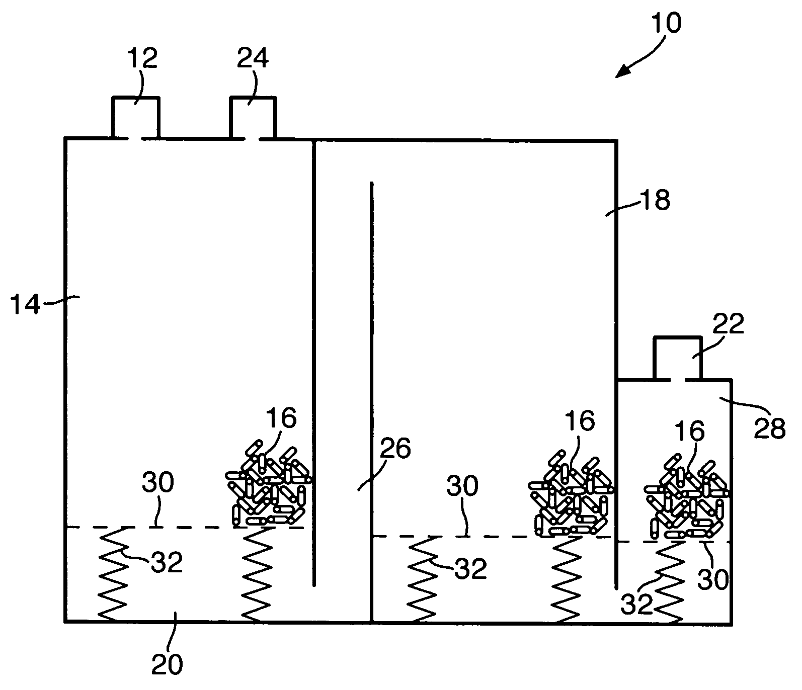
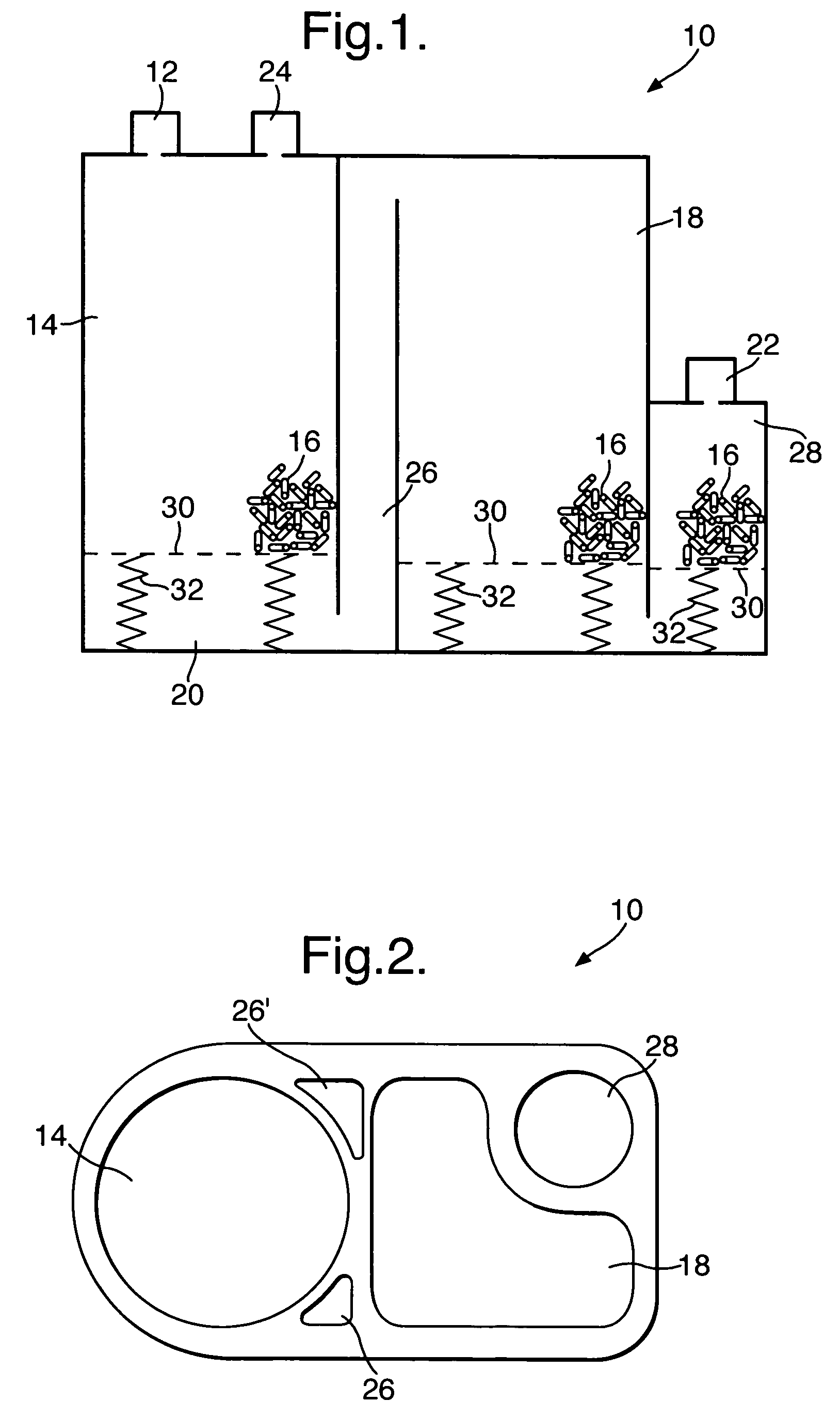
[0020]A preferred embodiment of an evaporative canister according to the invention is shown in FIG. 1. The evaporative canister shown in this embodiment is a vertical-placed type integrated canister 10 connected to a fuel tank (not shown). Evaporated fuel from the fuel tank is led to the evaporative canister 10 via an evaporated fuel passage and, optionally, a liquid-vapour separator (not shown). The latter traps the fuel in a liquid phase. The fuel in the vapour phase only is fed into the canister via a tank port 12. The air / fuel vapour mixture first flows through a first adsorbent chamber 14 comprising an adsorbent material 16, generally activated carbon, and then through a second adsorbent chamber 18 also comprising an adsorbent material 16. As the air / fuel vapour mixture flows through the first and second adsorbent chambers 14, 18, the fuel component of the air / fuel vapour mixture is stripped from the vapour mixture and purified air exits the canister 10 into atmosphere via an a...


PUM


Abstract

An evaporated fuel processing device (10), in particular for an internal combustion engine of an automotive vehicle, comprises a tank port (12) and an atmospheric port (22); a first adsorbent chamber (14) between the tank port (12) and the atmospheric port (22); and a second adsorbent chamber (18) between the first adsorbent chamber (14) and the atmospheric port (22), the first and second adsorbent chambers (14, 18) being filled with an adsorbent material (16). According to an important aspect of the invention, at least two elongate flow passages (26, 26′) are arranged in parallel between the first adsorbent chamber (14) and the second adsorbent chamber (18).

Description

FIELD OF THE INVENTION[0001]The present invention generally relates to an evaporated fuel processing device, in particular for an internal combustion engine of an automotive vehicle, comprising an evaporative canister.BACKGROUND OF THE INVENTION[0002]There are three main sources of polluting gasses from an internal combustion engine: engine exhaust, crankcase, fuel supply systems. In the fuel tank, the hydrocarbons that are continually evaporating from the fuel constitute a significant contributing factor to air pollution.[0003]To control the air pollution resulting from these emissions, governments establish quality standards and perform inspections to ensure that standards are met. Standards have become progressively more stringent, and the equipment necessary to meet them has become more complex. Emissions from the fuel tank are reduced by an evaporated fuel processing device, the heart of which is an evaporative canister of activated carbon capable of holding fuel vapour. In ope...

Claims


Application Information

Patent Timeline
Patent Type & Authority Patents(United States)
IPC IPC(8): B01D53/04F02M33/02F02M25/08
CPCF02M25/0854
Inventor ABIDI, MOSTAFALOEVENBRUCK, REMI BPELLETIER, KARINELEONARD, THOMASDE BIASIO, ENNIO
Owner DELPHI TECH INC
Why Eureka
Try Eureka