EMI noise reduction circuit and method for bridgeless PFC circuit

a technology of pfc circuit and emi noise reduction, which is applied in the direction of electric variable regulation, process and machine control, instruments, etc., can solve the problems of several constraints and achieve the effect of increasing the cos

Active Publication Date: 2007-05-08
INFINEON TECH AMERICAS CORP
View PDF6 Cites 59 Cited by
  • Summary
  • Abstract
  • Description
  • Claims
  • Application Information

AI Technical Summary

Benefits of technology

[0017]Two extra diodes, requiring an extra heat sink, make the circuit more expensive and are avoided by the circuit according to the present disclosure.

Problems solved by technology

Although the circuit of FIG. 10 can improve the bridgeless PFC circuit EMI performance, it suffers from several constraints.Two extra diodes need to be used.

Method used


Image

  • EMI noise reduction circuit and method for bridgeless PFC circuit
  • EMI noise reduction circuit and method for bridgeless PFC circuit
  • EMI noise reduction circuit and method for bridgeless PFC circuit

Examples


first embodiment

[0030]the invention is shown in FIG. 8.

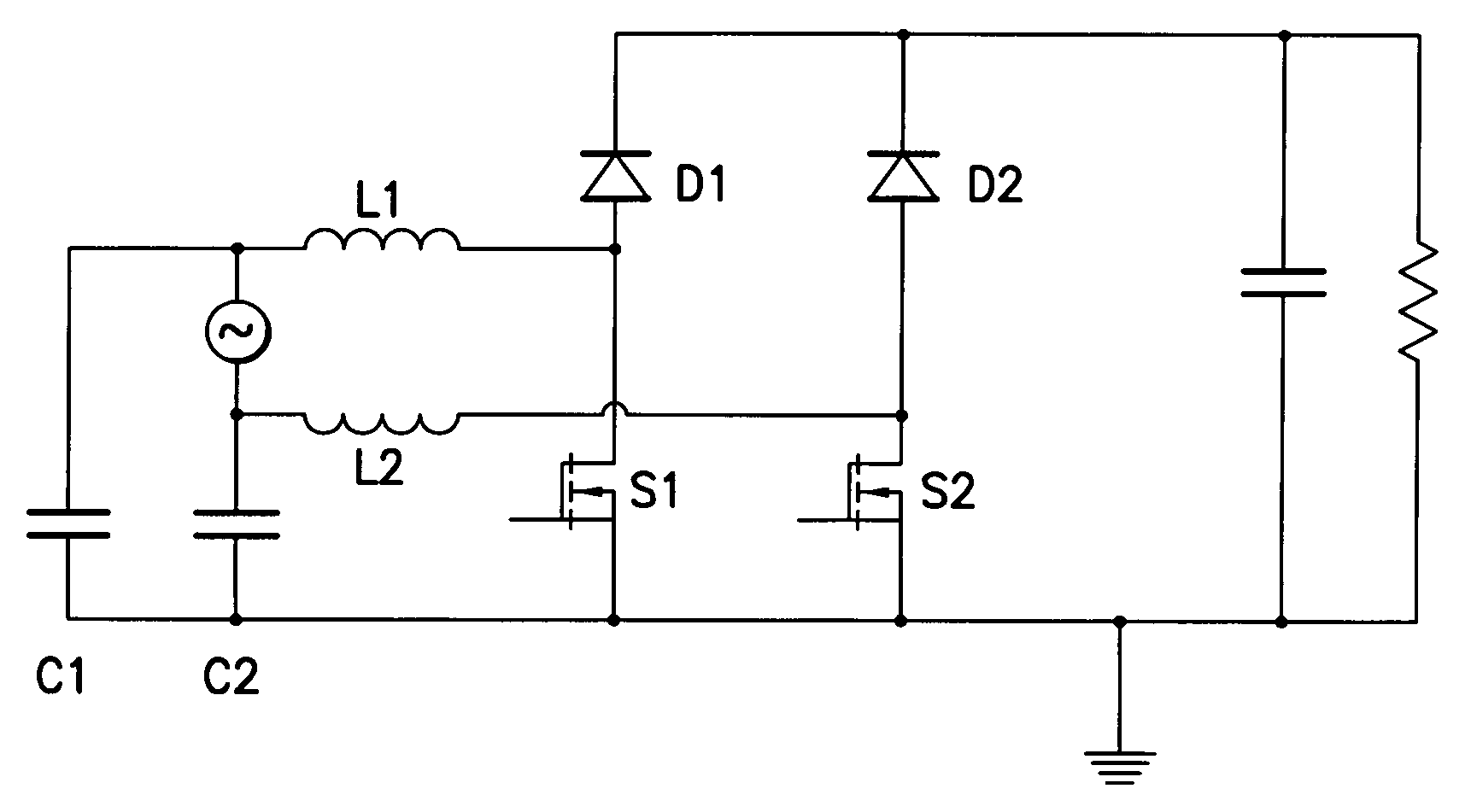
[0031]The equivalent circuits of the new circuit at each half line cycle are shown in FIGS. 9a and 9b, respectively. The capacitors C1 and C2 have the same capacitance and voltage rating at 600V DC, and they can be considered substantially shorted at the switching frequency, which means that their impedance at the switching frequency is much smaller than the boost inductor's impedance at the same frequency. Since the impedance of a capacitor decreases with increasing frequency, while the impedance of an inductor increases with frequency, the capacitor may be considered substantially to be a short circuit for the whole high frequency range, as compared with the boost inductor.

[0032]In another embodiment of the invention, some EMI improvement may be obtained by using only one capacitor; however, it is preferably to include both of the two capacitors.

[0033]The switches S1 and S2 may be MOSFETs, bidirectional switches, bidirectional MOSFETS, or GaN...


PUM


Abstract

A circuit and method for improving EMI noise performance in a bridgeless PFC boost converter. Such a converter comprises a boost inductor having a first end connected to a first AC input terminal and a second end connected to a first junction defined between the anode of a first diode and a first terminal of a first switch; a second terminal of the first switch connected to a common line; a parallel circuit of a capacitance and a load connected between the cathode of the first diode and the common line; a series circuit of a second diode and a second switch connected between the cathode of the first diode and the common line; and a second AC input terminal connected to a second junction defined between the anode of the second diode and the second switch. High-frequency EMI noise is bypassed by placing a first filter capacitor between the first AC terminal and the common line. A second boost inductor may be connected between the second AC input terminal and the second junction, and a second filter capacitor may be connected between the second AC terminal and the common line. The first and / or second filter capacitor has a lower impedance in a high frequency range than the corresponding first or second boost inductor. Preferably the first and second capacitors have substantially the same capacitance.

Description

CROSS REFERENCE TO RELATED APPLICATIONS[0001]The present application is based upon and claims priority of provisional application Ser. No. 60 / 635,793, filed Dec. 14, 2004, incorporated by reference.BACKGROUND OF THE INVENTION[0002]1. Field of the Invention[0003]The present invention relates to a circuit and method for improving EMI noise performance in a bridgeless PFC boost converter, and more particularly to an improvement including a bypass filter capacitor connected to an AC source terminal.[0004]2. Related Art[0005]A conventional bridgeless PFC circuit for power factor correction is shown in FIG. 1. As compared with the conventional PFC circuit including a bridge, shown in FIG. 2, the bridgeless PFC circuit reduces the number of semiconductor devices in the conduction path. In the conventional PFC circuit, there are three semiconductors in the current conduction path. As for the bridgeless PFC circuit, only two semiconductor devices are in any given conduction path. Both circui...

Claims


Application Information

Patent Timeline
Patent Type & Authority Patents(United States)
IPC IPC(8): H02M1/12H02M7/12
CPCH02M1/4225H02M1/44H02M3/1584Y02B70/126Y02B70/10H02M1/0085
Inventor SOLDANO, MARCOLU, BIN
Owner INFINEON TECH AMERICAS CORP
Why Eureka
Try Eureka