
Method and apparatus for registering palm pattern impression

a palm pattern and pattern technology, applied in the field of palm pattern impression registration methods and apparatuses, can solve the problems of not appearing clearly in some palm pattern impression images with lower image quality, affecting the accuracy of palm pattern impressions, and reducing the time required for collation, so as to simplify the process of splitting and narrow the search area.

Inactive Publication Date: 2007-05-08
NEC CORP
View PDF7 Cites 6 Cited by
  • Summary
  • Abstract
  • Description
  • Claims
  • Application Information

AI Technical Summary

Benefits of technology

[0012]The object of the present invention is to provide a method and apparatus for registering palm pattern impressions that can simplify the process of splitting a palm pattern impression into multiple regions by eliminating the necessity of the intervention of expert human hands, that can also support the use of a database built through the conventional method of splitting a palm pattern impression into three regions, i.e., interdigital region, thenar region, and hypothenar region, and that can reduce the time required for collation by narrowing the search area.
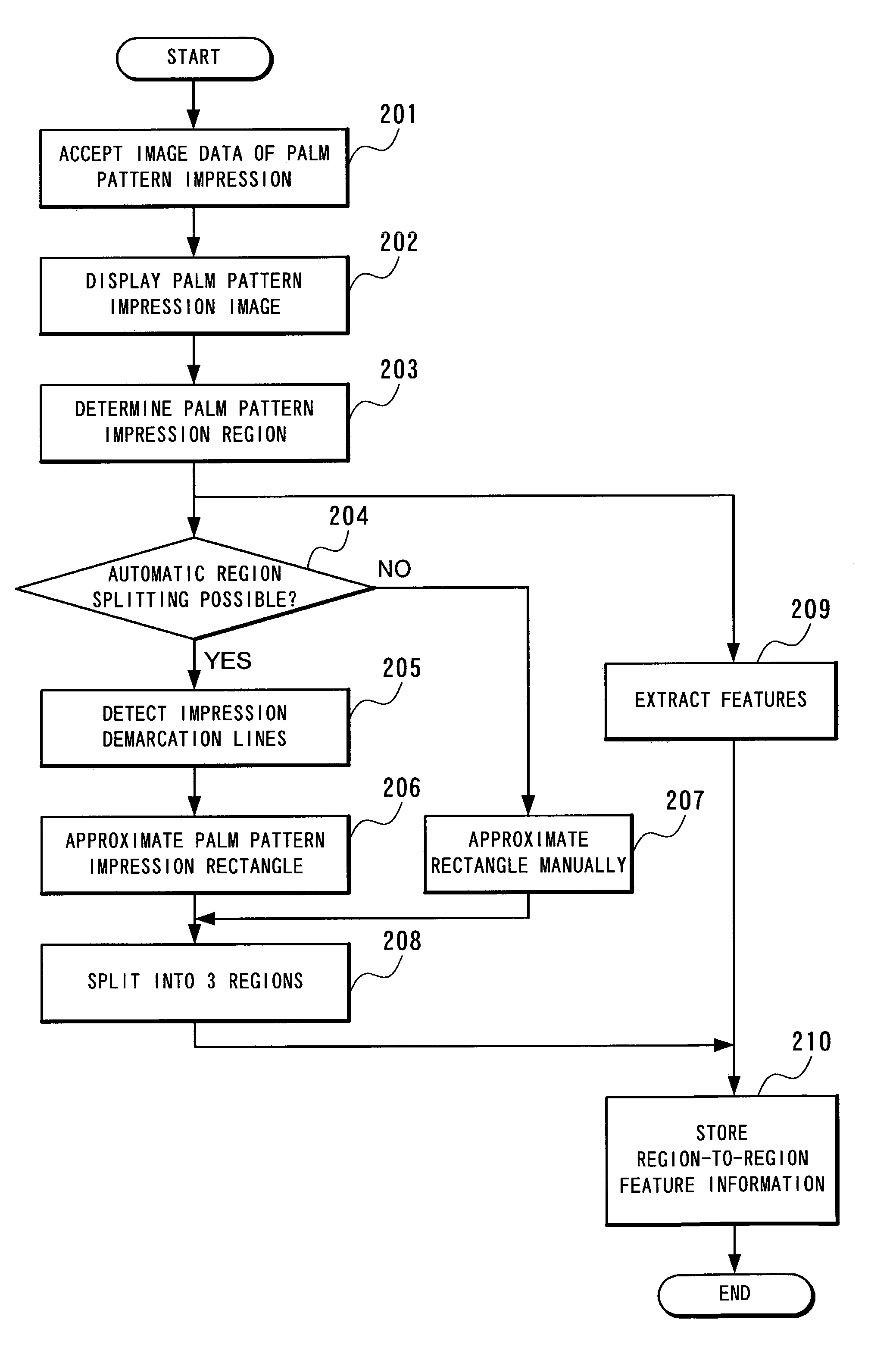
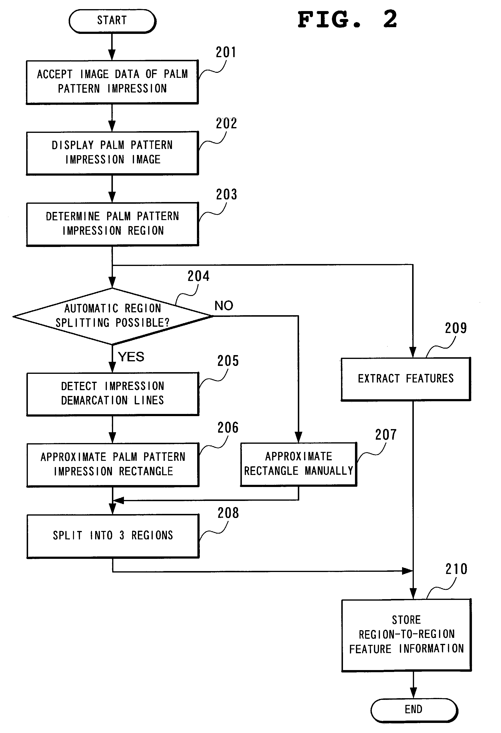
[0048]According to the present invention, in the process of splitting a palm pattern impression into multiple regions, the region splitting process can be simplified to the extent that it does not require expertise concerning palms, because the present invention determines the above-mentioned regions by detecting a rectangular area enclosed by the demarcations between palm patterns and the background and then combining the smaller segments of this rectangular area. By this, it allows an ordinary person to process data after receiving some training or enables a computer to process data automatically without intervention of experts.
[0050]The present invention can thus reduce the time required for the process of registering palm pattern impressions by minimizing the requirements for the intervention of experts. In addition, the cost and time for re-registering the new data of palm impressions become unnecessary, because the registered data of palm impressions that were split using the conventional art into three regions, i.e., interdigital region, thenar region, and hypothenar region, can be utilized without any modifications.

Problems solved by technology

The above-described conventional methods and apparatuses for registering palm pattern impressions, however, hold several problems, as described below.
The first problem is that the points to serve as reference points, e.g., the middle point between the middle finger and the ring finger, the arm trident, the point of intersection between the Life line and the impression end, and the point of intersection between the Heart line and the impression end, do not appear clearly in some palm pattern impression images with lower image quality.
The second problem is that the process of splitting a palm pattern impression into regions relies on visual inspection.
In other words, these arts require the intervention of human hands during the region splitting process for the registration of the images of impressed palm patterns, requiring an enormous number of man-hours by experts to build a large-scale palm pattern database.
The third problem is that the need to utilize the data registered in this palm pattern database may very often arise when palm pattern data are re-registered using a new region splitting method.
Since the palm pattern database has already been built using the above-mentioned art, difficulties should be encountered in meeting such need.

Method used


Image

  • Method and apparatus for registering palm pattern impression
  • Method and apparatus for registering palm pattern impression
  • Method and apparatus for registering palm pattern impression

Examples


Embodiment Construction

[0062]The preferred embodiment of the present invention will be discussed hereinafter in detail with reference to the accompanying drawings. In the following description, numerous specific details are set forth in order to provide a thorough understanding of the present invention. It will be obvious, however, to those skilled in the art that the present invention may be practiced without these specific details. In other instance, well-known structures are not shown in detail in order to unnecessary obscure the present invention.

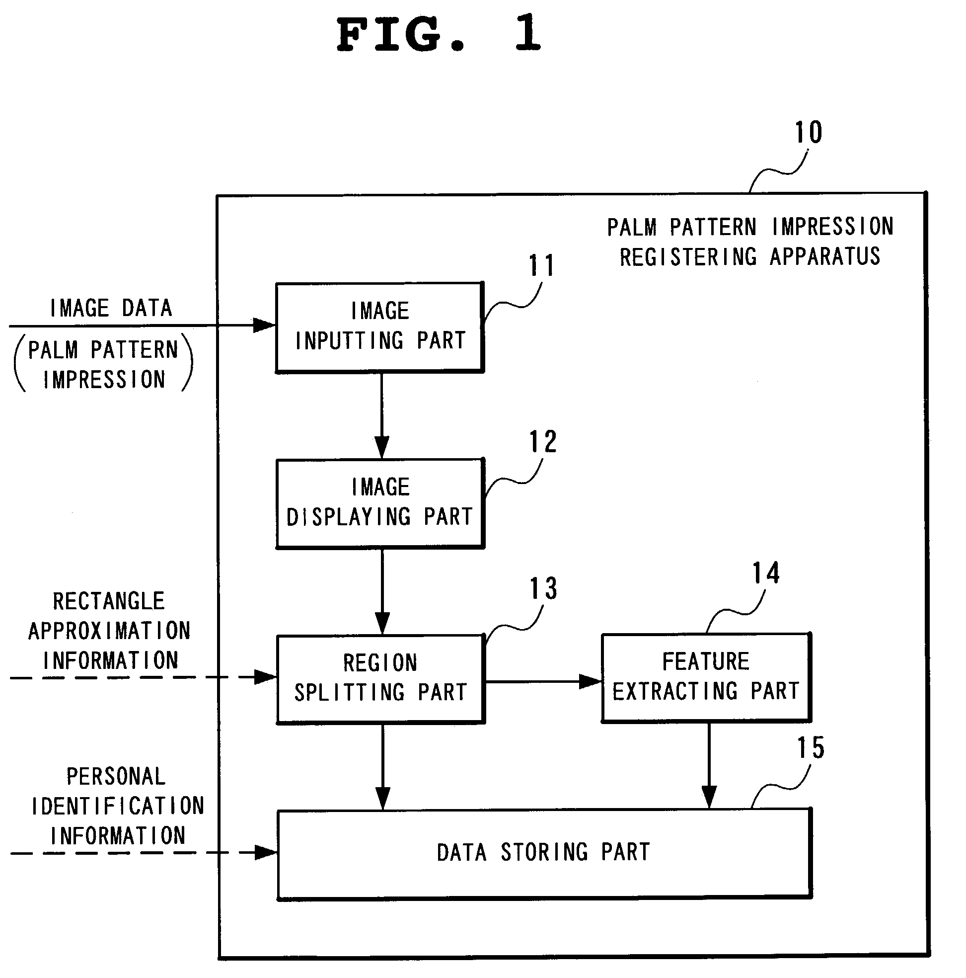
[0063]FIG. 1 is a block diagram showing an apparatus for registering palm pattern impressions according to one embodiment of the present invention.

[0064]The palm pattern impression registering apparatus 10 according to this embodiment shown in FIG. 1 is provided with an image inputting part 11, e.g., scanner and camera, for inputting palm pattern impressions as image data; an image displaying part 12, e.g., display, for displaying image data of palm pattern i...


PUM


Abstract

A method detecting a rectangle enclosed by a pair of parallel horizontal lines that are demarcation lines between the palm pattern impression and the background in wrist-side and fingertip-side, and a pair of parallel vertical lines are orthogonal to the horizontal lines and are demarcation lines between the palm pattern impression and the background in thumb-side and little-finger-side. The method splits the rectangle into, three segments horizontally by four segments vertically, and then splits the palm pattern impression into three regions, the first being a combination of three segments horizontally by two segments vertically located toward the fingertip among the segments, the second being a combination of two segments horizontally by three segments vertically located toward the thumb and the wrist among the segments, and the third region being a combination of two segments horizontally by three segments vertically located toward the little finger and the wrist among the segments.

Description

BACKGROUNDS OF THE INVENTION[0001]1. Field of the Invention[0002]The present invention relates to a method and apparatus for registering palm pattern impression impressed by each of different individuals who are subject to personal identification by use of a computer system, for the purpose of personal identification. In particular, the present invention relates to a method and apparatus for registering palm pattern impressions through simplified means that does not rely on human hands, thereby reducing the time required for the registration process.[0003]2. Description of the Related Art[0004]Fingerprints are said to be the physical feature information most commonly used in personal identification and personal authentication for the purpose of verifying that an individual is really the person whom he or she claims to be. Features that can be obtained from fingerprint ridges (bifurcations and endpoints) vary from person to person and do not change for life.[0005]Because of these cha...

Claims


Application Information

Patent Timeline
IPC IPC(8): G06K9/00G05B19/00A61B5/117G06V40/13G06T7/00G06T7/60
CPCG06K9/00013G06V40/13
Inventor MIZOGUCHI, MASANORI
Owner NEC CORP
Learn More