Screen basket and shale shakers

a technology of shale shakers and baskets, which is applied in the direction of filtration separation, well accessories, and separation processes, etc., can solve the problems of shale shaker capacity limits, weight, viscosity and gel problems in the mud, and increase the wear of mud pumps and other mechanical equipment used for drilling, so as to reduce the load on the horizontal screen(s), increase the available screening area, and improve efficiency and productivity

Inactive Publication Date: 2007-05-15
VARCO I P INC
View PDF60 Cites 60 Cited by
  • Summary
  • Abstract
  • Description
  • Claims
  • Application Information

AI Technical Summary

Benefits of technology

[0025]A basket as described above according to the present invention provides more screening area to treat material and separate its components than a conventional basket with the same footprint. By thus increasing the available screening area, the load on the horizontal screen(s) is reduced; their efficiency, and productivity are increased; and total throughput for the basket is increased. Shaker or screen capacity is typically determined by the position of a “fluid-end point”. The fluid end-point is the point where the fluid pool stops on the screen surface near the shaker's discharge end. As the fluid-end point moves closer to the discharge end, discharged solids can become too wet, risking whole mud losses over the screen. A typical rule of thumb for optimum shaker capacity specifies covering 66% or less of the shaker's screen surface. The integration of vertical screens into a shaker basket according to the present invention shortens the length of the fluid pool, effectively increasing shaker capacity.
[0041]A system with any such basket that has relatively increased throughput and which increases screen life.

Problems solved by technology

If drilled solids are not removed from the mud used during the drilling operation, recirculation of the drilled solids can create weight, viscosity, and gel problems in the mud, as well as increasing wear on mud pumps and other mechanical equipment used for drilling.
Shale shakers have capacity limits.
Exceeding a capacity limit means excessive mud will be discharged over the ends along with the solids.
The solids capacity limit is encountered when drilling soft, gummy formations.
The thicker the mud, the lower the GPM capacity.

Method used


Image

  • Screen basket and shale shakers
  • Screen basket and shale shakers
  • Screen basket and shale shakers

Examples


Embodiment Construction

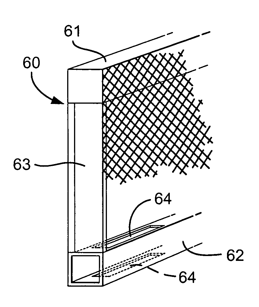
[0053]Referring now to FIGS. 5A–5D, a screen-supporting basket 10 for a vibratory separator or shale shaker has two spaced-apart side walls 12, 14 and an end wall 16 between them. Typical vibrator apparatus 20 is connectible to the basket 10. An end screen 40 is mounted in channels 22, 24 on opposite sides of the end wall 16. Screen mounting apparatus 46 may be any such known apparatus.

[0054]In one aspect the channels 22, 24 are open at the top so the screen 40 can be introduced into the space between the channels 22, 24. Optional removable blocks 26, 28 on the interior of the basket hold the screen 40 in place in the channels; and optional crown bars 32 on the screen 40's exterior provide support for the screen 40. In one aspect each crown bar 32 has a rubber part 34 that contacts the screen 40. Screening material on the screen 40 (as on any screen according to the present invention) may be any suitable known screening material, including, but not limited to one, two, three or more...


PUM

PropertyMeasurementUnit
weightaaaaaaaaaa
viscosityaaaaaaaaaa
movementaaaaaaaaaa

Abstract

A screen mounting basket for a vibratory separator for separating components of material introduced into the basket, the vibratory separator including a collection receptacle beneath the basket, the basket including two opposed spaced-apart side walls having first ends and second ends, the first ends spaced-apart by spaced-apart end walls connected to each of the side walls, a basket bottom between the two spaced-apart side walls, at least one screen assembly positioned vertically in the basket for interceptions material introduced into the basket and for screening said material, and the at least one screen assembly extending from one side wall of the basket to the other.

Description

RELATED APPLICATION[0001]This is a continuation-in-part of U.S. Ser. No. 10 / 169,484 filed Sep. 16, 2002 (issued as U.S. Pat. No. 6,863,183 on Mar. 8, 2005) which is a division of U.S. application Ser. No. 09 / 716,176 filed Nov. 17, 2000, issued as U.S. Pat. No. 6,371,301 B1 on Apr. 16, 2002; and this application claims priority from PCT Application No. PCT / GB01 / 04667, Int'l Publication No. WO 02 / 40186 A1, filed Oct. 19, 2001, all of which are incorporated fully herein for all purposes and from all of which the present invention claims priority under the Patent Laws.BACKGROUND OF THE INVENTION[0002]1. Field of the Invention[0003]The present invention is directed to vibratory separators, screen-supporting baskets for them, and, in certain particular embodiments, to shale shakers for treating drilling fluid, screen-supporting baskets for them, screens for such separators and shakers and methods of using such screens, shakers, baskets, and separators.[0004]2. Description of Related Art[0...

Claims


Application Information

Patent Timeline
Patent Type & Authority Patents(United States)
IPC IPC(8): B07B1/28B01D33/03B07B1/46E21B21/06
CPCB01D33/033B07B1/46B07B1/4609B07B1/4663B07B1/4672B07B1/469E21B21/065B01D33/0376B01D33/37B01D33/745B01D33/742B07B2201/04B07B2230/01
Inventor SCHULTE, DAVID L.GRICHAR, CHARLES N.MCCLUNG, III, GUY L.
Owner VARCO I P INC
Why Eureka
Try Eureka