Filtration system

Inactive Publication Date: 2007-05-15
MULVEY KEVIN
View PDF7 Cites 4 Cited by
  • Summary
  • Abstract
  • Description
  • Claims
  • Application Information

AI Technical Summary

Benefits of technology

[0023]An object of the present invention is to provide a primary filtration array and an efficient second remedial array that is easily fabricated and can be supplied at low cost.
[0024]The present invention is a filtration system contained in a tank having a rounded base that eliminates the stagnant area usually found in the area of the rounded base. In the normal operation of a filtration system, the water passed through the filter media where it deposits impurities and debris. The medium must be cleaned periodically and this is done during the backwash cycle where water is passed through in the reverse direction and dumped to eliminate the debris from the system.
[0025]Most filtration system include a first pipe array located above the rounded base which allows the back washing of the upper portion of the tank, but leaves the base area below the first pipe array stagnant and subject to the growth of harmful bacteria. The present invention adds a second or remedial array which is configured to follow the contours of the rounded base of the tank permitting it to cover more area. This second array is located in the base area and therefore is able to eliminate the stagnant area of the tank during the backwash cycle.
[0026]In the present invention, a downcorner (pipe section) from the header is split into 4 remedial horizontal lines. Each remedial “horizontal

Problems solved by technology

Unfortunately, the water used for back washing passes upward through the media from the laterals.
When back on shore, all had a fever so fierce that one received brain damage and another died.
This problem exists in many currently used filters and is obviously an extremely important health matter.
The reason the laterals of the first array are generally not positioned lower in the tank in the rounded base of the tank is that laterals of a length that could be accommodated in an area above the tank base cannot be accommodated in the base tank because of interference with the rounded wall

Method used


Image

  • Filtration system
  • Filtration system
  • Filtration system

Examples


Embodiment Construction

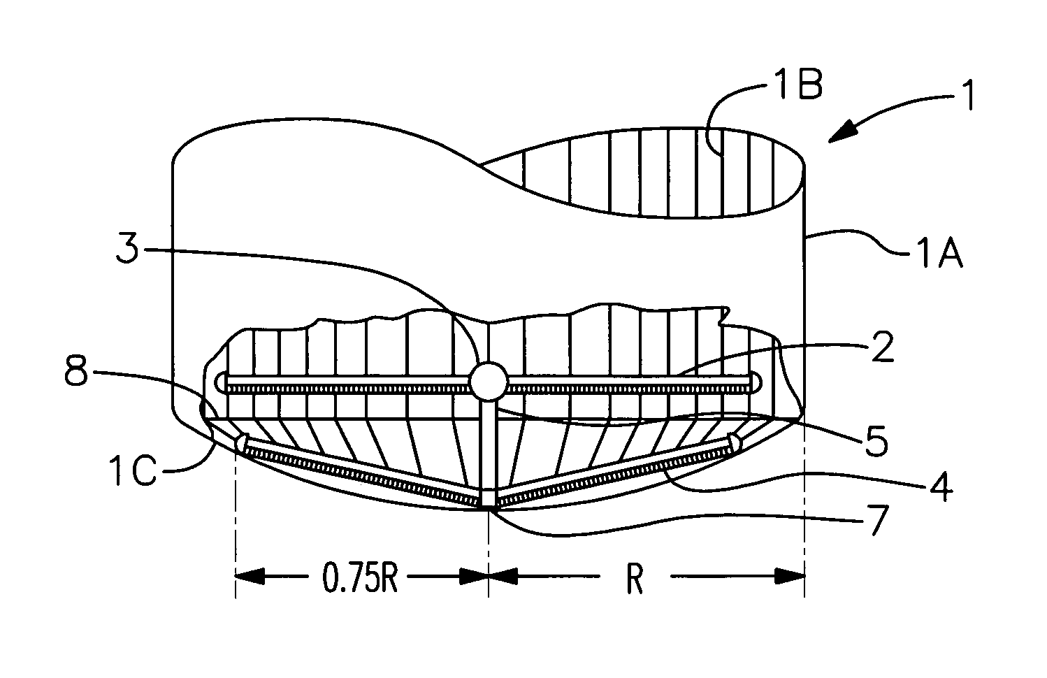
[0028]FIG. 1 is a side view of a tank used in a filtration system showing the typical rounded base of the tank where stagnation usually occurs and also showing the location of the header of a first array which is typically positioned above the stagnation area. In this Figure, the tank is cut away on one side to show a first and a second array used in this filtration system. This Figure includes a tank 1 having an outside wall 1A and inside wall 1B, a first pipe array 2, a second pipe array 4, a header 3, a downcorner 5 connecting the first array to the second at a five way cross connector 7.

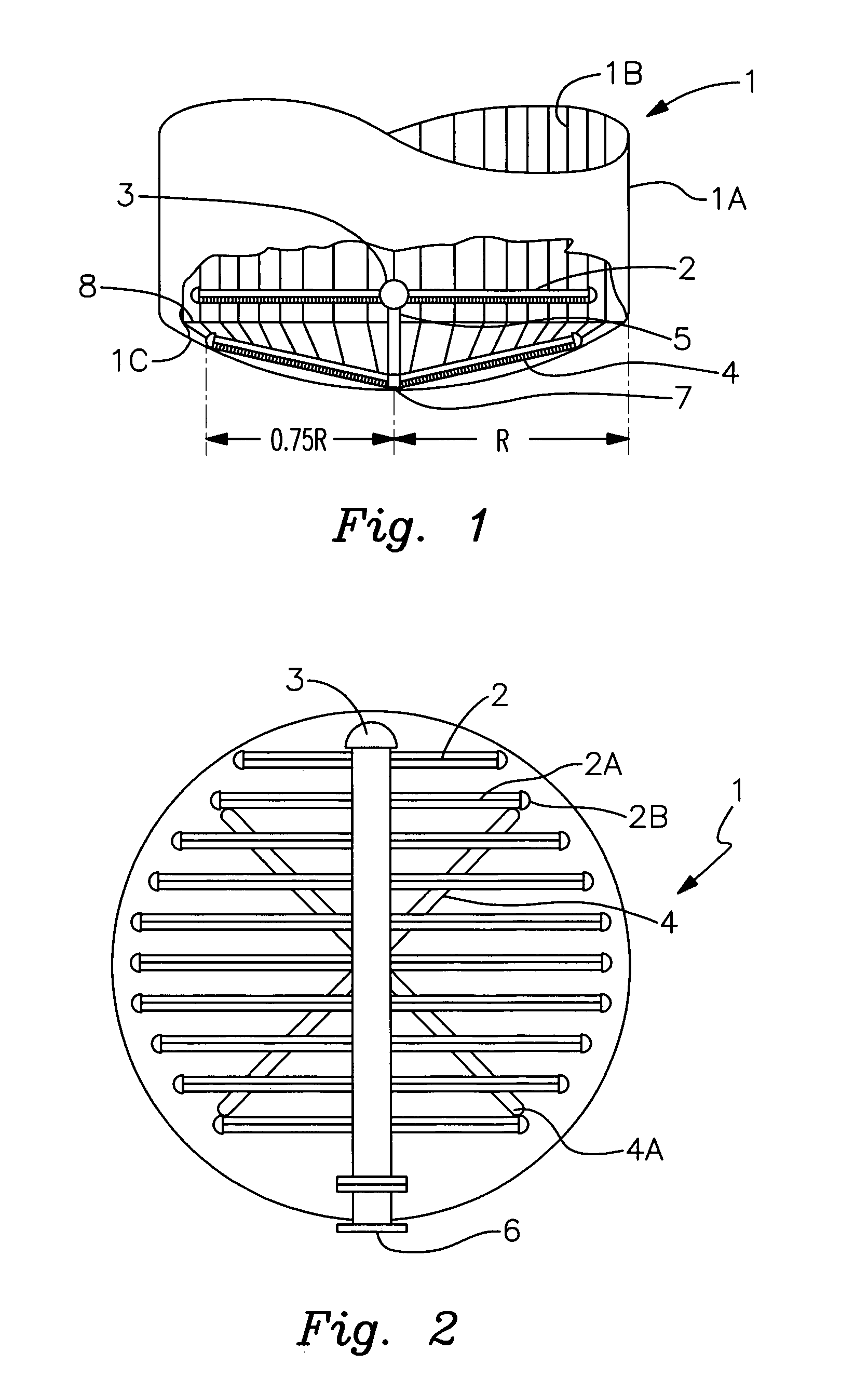
[0029]FIG. 2 is a top view of the tank and filtration system shown in FIG. 1 with the top of the tank removed to shown the first and second arrays. This Figure also shows that the header 3 is connected to the outside of the tank by means of a connector 6. The first array is formed of a series of horizontal laterals which are connected at one end to the header 3. Their opposite ends are capped. Th...


PUM

PropertyMeasurementUnit
Timeaaaaaaaaaa
Lengthaaaaaaaaaa
Areaaaaaaaaaaa

Abstract

A filtration system for cleaning a fluid, typically water, that is contained in a tank having a rounded base and which cleans, during the backwash cycle, the filter media and, in particular, cleans the media in a usually stagnant area found in the rounded base of the tank. Most filtration system include a first pipe array located above the rounded base which provide for backwashing of the upper portion of the tank, but leaves the base area below the first pipe array stagnant and subject to the growth of harmful bacteria. The present invention adds a second array which is located in the base area and therefore is able to clean during the backwash cycle, an area that is left stagnant in most other systems. The second array is configured to follow the contours of the base of the tank to give it a greater cross sectional area than a flat array. This configuration results in greatly improved effectiveness over that provided by the conventional single flat array.

Description

[0001]This application claims the benefit of U.S. Provisional Application Ser. No. 60 / 473,216, filed on May 27, 2003.BACKGROUND [0002]1. Field[0003]The present invention relates to liquid filtration systems and more particularly to such systems that are housed within tanks and are designed to eliminate stagnation that often occurs in the base of the tank.[0004]2. Prior Art[0005]Most prior art liquid filtration systems include a closed tank with an outer skin or shell that is used to house the filtrations system. Such filtration systems are often used to clean the water used in swimming pools. The tanks are typically cylindrical with rounded, rather than flat, ends. The rounded ends allow less material to be used in the tank wall to withstand the pressure in the tank. The tanks may be positioned vertically with a rounded end being located at the bottom of the tank or the tank may be positioned horizontally where it will still have a rounded bottom.[0006]Within the tank, immediately a...

Claims


Application Information

Patent Timeline
IPC IPC(8): B01D24/46B01D24/14
CPCB01D24/14B01D24/4631
Inventor MULVEY, KEVIN
Owner MULVEY KEVIN
Why Eureka
Try Eureka