High pressure resistance body element

a resistance body and high-pressure technology, applied in the direction of resistor housing/enclosement/embedding, base element modification, instruments, etc., can solve the problems of unavoidable vibration phenomena, inability to eliminate hazard in tests, and varied detrimental effects

Active Publication Date: 2007-05-15
KOUKEN CO LTD
View PDF8 Cites 6 Cited by
  • Summary
  • Abstract
  • Description
  • Claims
  • Application Information

AI Technical Summary

Benefits of technology

[0042]In addition, this fact suppresses the occurrence of vibration, eliminates the need for vibration-proof rubbers, and mitigates considerably hazard in the tests. Further, the absence of sharp edges of protrusions like the fins used in the prior art example, increases dielectric strength, and enables to avoid the hazard of dielectric breakdown; and the fixation of a high-voltage resistor element to a supporter by means of the insulating sleeve encasing the same contributes further to blocking dielectric breakdown and other advantageous effects.

Problems solved by technology

The fin 9, which is habitually provided for the high-voltage resistor element 1′ of this kind, is extremely effective for use in a low-voltage resistor element, however, it has not been elucidated that the fin 9 causes various detrimental effects as described below.
Specifically, because the fin 9 provides a resistance to the ventilation, an air turbulence and a disturbed air stream are produced in the high-voltage load resistor unit 13, and thus the vibration phenomena that occur as a result thereof is unavoidable.
In the prior art example, this phenomena is avoided by use of the vibration-proof rubber 15, however, the hazard in the tests cannot yet be eliminated.
Moreover, because the insulating material 5′ hermetically sealed in the outer tube 2′ of the high-voltage resistor element 1′ is in a powdery state, it shifts to one side by such an external force vibration, which results in the impossibility of realizing a uniform thickness covering and the partial insufficiency of the insulation, and finally acts as a trigger for a dielectric breakdown.
In addition, because of the powdery state, the resistive heat-generating wire 3 being red hot in operation can easily burnout or disconnect by the vibration, which results in the lack of a heat resistance.
Nevertheless, the cause of troubles, which was often brushed off as an erroneous operation made by the operator, has not been thoroughly elucidated.
Thus, with the conventional high-voltage resistor element 1′, it has been impossible to carry out the load characteristic tests without involving hazard.
In addition, the fin 9 makes it difficult to see inside the rectangular frame 12 from above, which presents an interference in maintenance, inspection and adjustment, and further, because only the burnt or disconnected high-voltage resistor element 1′ cannot be laterally extracted from the rectangular frame 12, a partial replacement could not be carried out on the working site.

Method used


Image

  • High pressure resistance body element
  • High pressure resistance body element
  • High pressure resistance body element

Examples


Embodiment Construction

[0049]An embodiment of the present invention will be described with reference to the drawings.

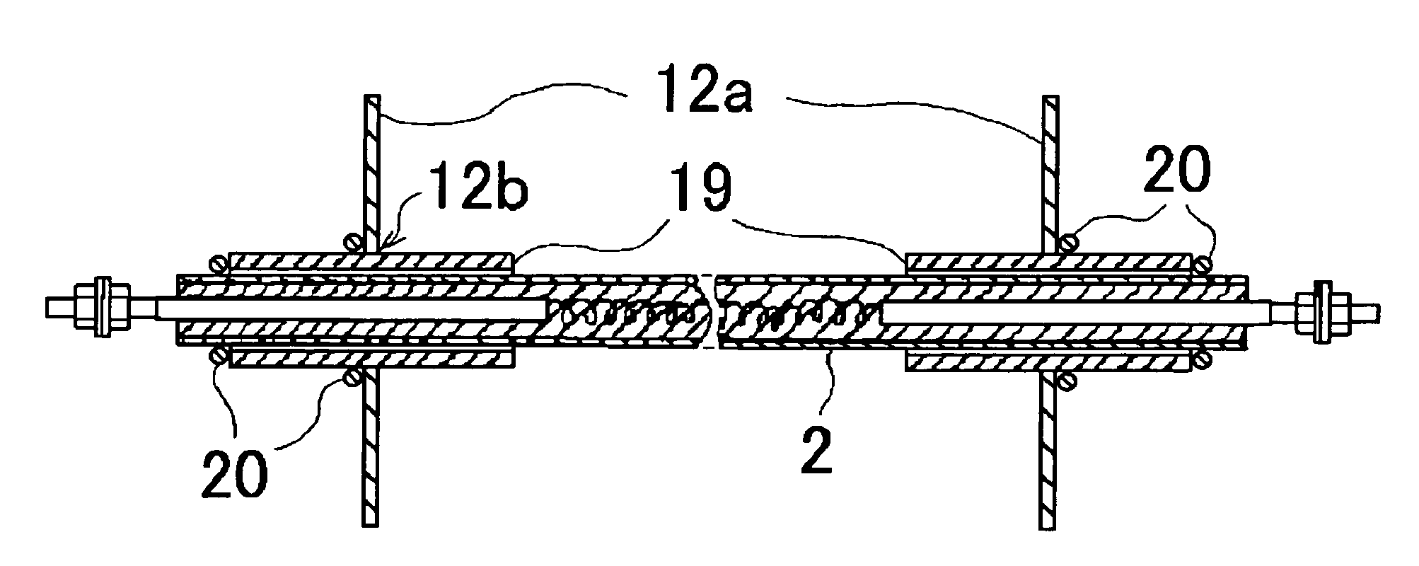
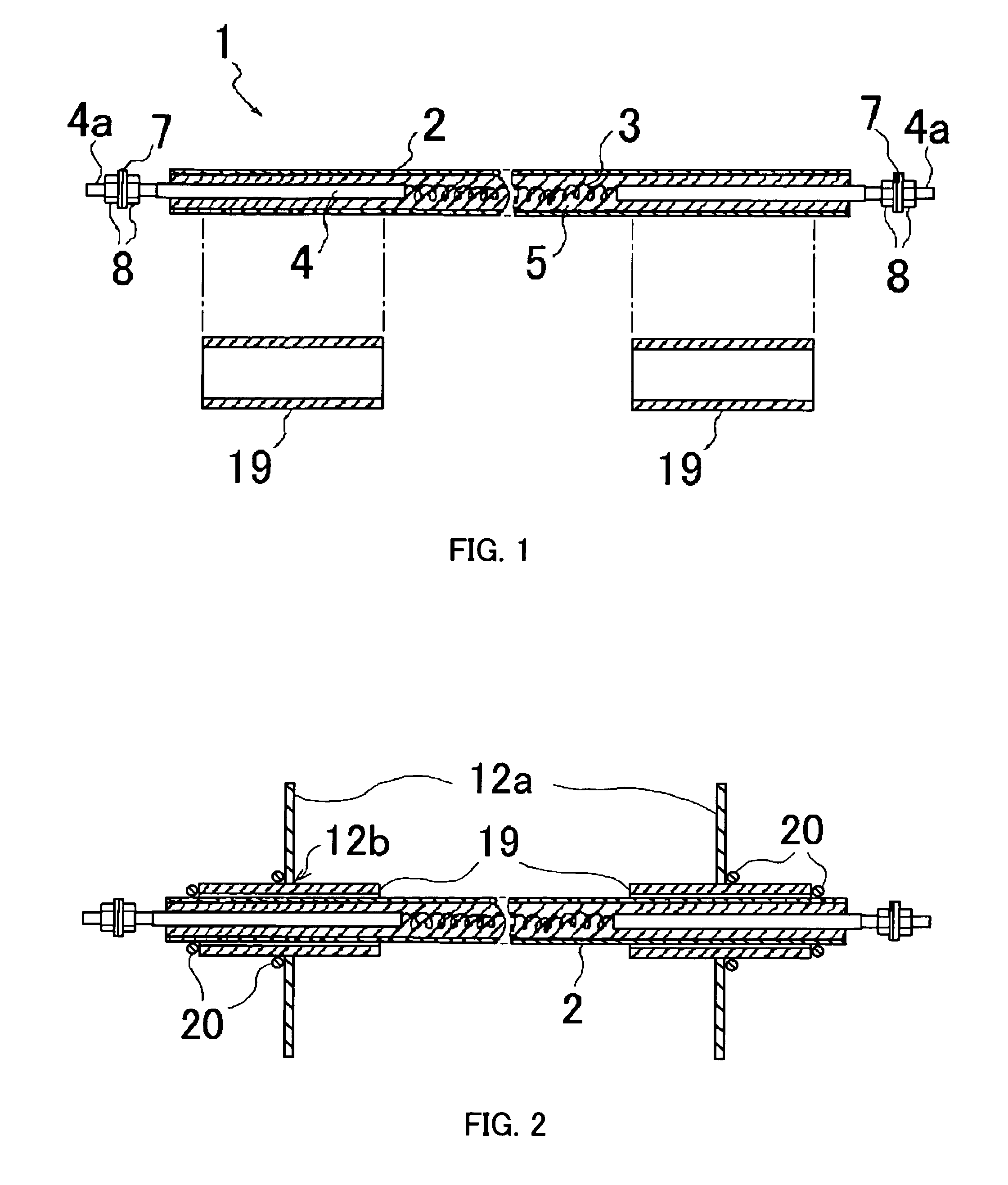
[0050]FIG. 1 is a fragmentary cutaway side view illustrating a high-voltage resistor element from which an insulating sleeve is disassembled and removed according to the embodiment of the present invention, and FIG. 2 is a fragmentary cutaway side view illustrating a high-voltage resistor element, both ends of which are penetratingly bridged between arrangement boards.

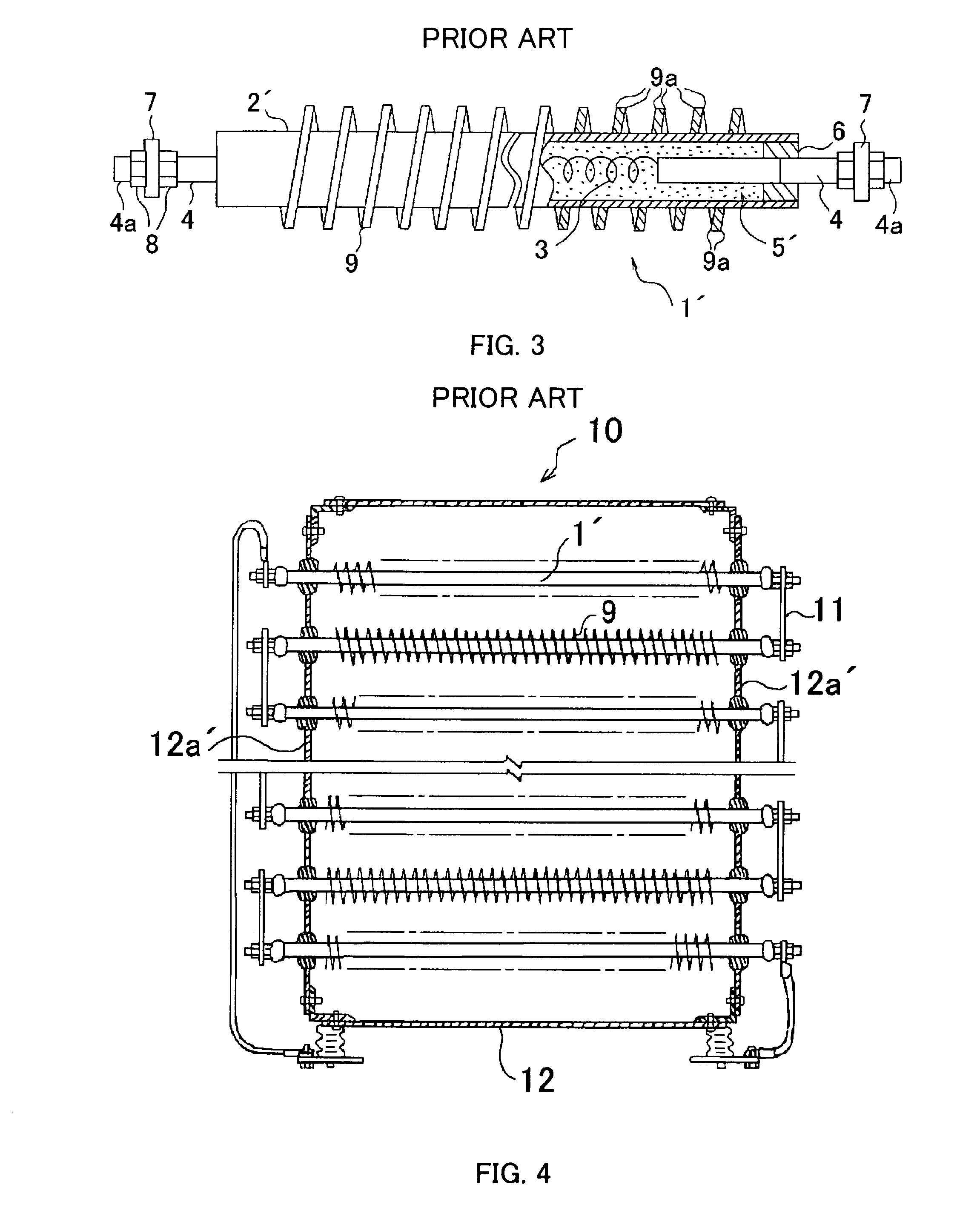
[0051]In the present embodiment, however, identical parts are marked with the identical numerals, and some of them without prime(′) denote the corresponding parts in the prior art example.

[0052]In the figures, numeral 1 denotes a high-voltage resistor element in the present embodiment; and 2 an outer tube made of metal, which employs a currently used external sheath for low voltage use serving as an overall protection cover for an insulating material 5, in which the surface is formed smooth to suppress the occurrence of discha...


PUM


Abstract

A high-voltage resistor element which is superior to heat resistance, dielectric breakdown strength, vibration resistance and durability performance, and is advantageous to maintenance, inspection, adjustment, replacement and repair, is made up of: a cylindrical outer tube made of metal; a resistive heat-generating wire in a coiled shape tensionally extending between inner ends of electrode rods inserted respectively from both ends of the outer tube; an insulating material filing up a space between the resistive heat-generating wire with the electrode rods and the internal surface of the outer tube and fired; and insulating sleeves extractably encasing and anchored in the portions adjacent to the both ends of the outer tube penetratingly bridging between arrangement boards.

Description

TECHNICAL FIELD[0001]The present invention relates to a high-voltage resistor element as a high-voltage metallic resistor to be used in load characteristic tests of a high-voltage power generator.BACKGROUND ART[0002]Heretofore, as a load resistor to be used in load characteristic tests of a power generator, that which employs a high-voltage resistor element 1′ having a fin 9 as shown in FIG. 3 has been utilized. In the same figure, numeral2′ denotes an outer tube in a cylindrical shape, which is formed to be approximately 1 m long.[0003]And numeral 3 denotes a resistive heat-generating wire; 4 an electrode rod; and 5′ an insulating material filling up the space between the resistive heat-generating wire 3 with the electrode rod 4 and the internal surface of the outer tube 2′, and hermetically sealed with an end sealing member 6. This insulating material 5′ is in a powdery state, and has a function of insulating the outer tube 2′ from the resistive heat-generating wire 3 with the ele...

Claims


Application Information

Patent Timeline
Patent Type & Authority Patents(United States)
IPC IPC(8): H01C1/03G01R1/20G01R31/34H01C1/02H01C3/14
CPCG01R1/203H01C3/14H01C1/028H01C1/02G01R31/343H01C13/02
Inventor MATSUMOTO, KESAFUMI
Owner KOUKEN CO LTD
Why Eureka
Try Eureka