Metamaterial scanning lens antenna systems and methods

a scanning lens and metal material technology, applied in the field of antennas, can solve the problems of spherical aberration, large volume of mechanical or electronic systems required to scan the antenna or produce multiple beams, and high cost, and achieve the effect of a negative index of refraction

Inactive Publication Date: 2007-05-15
THE BOEING CO
View PDF4 Cites 294 Cited by
  • Summary
  • Abstract
  • Description
  • Claims
  • Application Information

AI Technical Summary

Benefits of technology

[0007]f=1n-1The metamaterial lens directs at least one generated wave. Because the present invention uses a metamaterial lens with much larger focusing power, an antenna can be formed having a relatively small focal length, thereby allowing the antenna to be produced in a smaller overall package than conventional scanning lens antennas without requiring the additional complexity or exhibiting the usual amount of spherical aberrations.
[0008]In accordance with further aspects of the invention, the system includes a user interface that is coupled to the controller. The user interface component allows a user to generate an instruction signal that the controller uses to generate the control signal.

Problems solved by technology

Typically, the mechanical or electronic systems required to scan the antenna or produce multiple beams are bulky, complex, and expensive.
A thin lens with a long focal length minimizes pattern distortions but will lose power due to spill over and will require a large rigid structure to support the lens and radiator.
Shortening the focal distance requires a more complex series of lenses or results in spherical aberrations.

Method used


Image

  • Metamaterial scanning lens antenna systems and methods
  • Metamaterial scanning lens antenna systems and methods
  • Metamaterial scanning lens antenna systems and methods

Examples


Embodiment Construction

[0016]The present invention relates to antennas, and more specifically, to systems and methods for radiating radar signals, communication signals, or other similar signals. Many specific details of certain embodiments of the invention are set forth in the following description and in FIGS. 1–7 to provide a thorough understanding of such embodiments. One skilled in the art, however, will understand that the present invention may have additional embodiments, or that the present invention may be practiced without several of the details described in the following description.

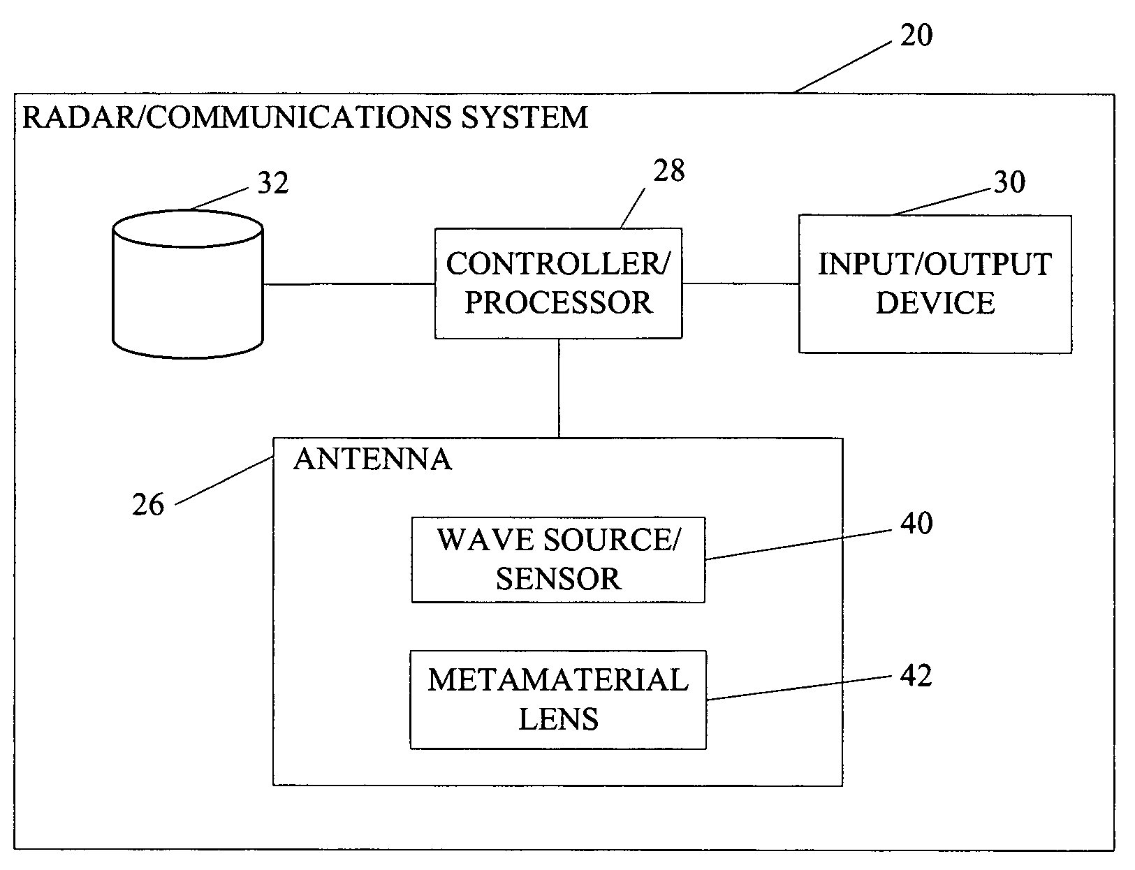
[0017]FIG. 1 illustrates a radar or communication system 20 for performing transmission and reception of signals. The system 20 includes an antenna 26, a controller / processor 28, an input / output device 30, and a storage unit 32. The controller processor 28 is operatively coupled to the antenna 26, the input / output device 30, and the storage unit 32.

[0018]The controller processor 28 may be a radar or communications p...


PUM


Abstract

The present invention is directed to systems and methods for radiating radar signals, communication signals, or other similar signals. In one embodiment, a system includes a controller that generates a control signal and an antenna coupled to the controller. The antenna includes a first component that generates at least one wave based on the generated control signal and a metamaterial lens positioned at some predefined focal length from the first component. The metamaterial lens directs the generated at least one wave.

Description

GOVERNMENT LICENSE RIGHTS[0001]This invention was made with Government support under a U.S. government contract number: MDA972-01-2-0016. The Government has certain rights in this invention.FIELD OF THE INVENTION[0002]This invention relates to antennas, and, more particularly to more efficient and compact scanning lens antennas.BACKGROUND OF THE INVENTION[0003]High and medium gain antennas that can be scanned or can produce multiple simultaneous beams are needed for a variety of mobile communications and sensor applications. Typically, the mechanical or electronic systems required to scan the antenna or produce multiple beams are bulky, complex, and expensive.[0004]Conventional scanning lens antennas use a dielectric lens to collimate the spherical wave from a small (low gain) radiator into a narrow beam (higher gain) plane wave. Shifting the location of the feed point of the radiator will scan the antenna beam over limited range of angles. Pattern quality is a function of the focal...

Claims


Application Information

Patent Timeline
Patent Type & Authority Patents(United States)
IPC IPC(8): H01Q19/06
CPCH01Q19/062H01Q15/0086
Inventor DAVIS, MARK R.GREEGOR, ROBERT B.LI, KINNIELSEN, JEAN A.PARAZZOLI, CLAUDIO G.TANIELIAN, MINAS H.
Owner THE BOEING CO
Why Eureka
Try Eureka