
Method for detecting grid in block-based compressed video

a block-based compressed video and grid technology, applied in the field of video signal processing, can solve the problems of inability to properly remove blocking artifacts, and based encoding techniques that introduce blocking artifacts between block boundaries

Inactive Publication Date: 2007-05-15
SAMSUNG ELECTRONICS CO LTD
View PDF6 Cites 12 Cited by
  • Summary
  • Abstract
  • Description
  • Claims
  • Application Information

AI Technical Summary

Benefits of technology

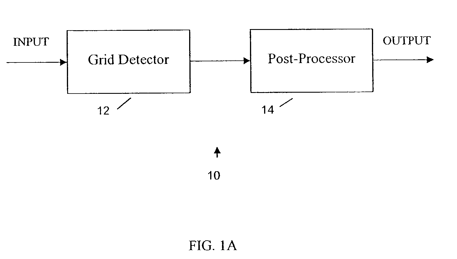
[0005]The present invention addresses the above needs. An object of the present invention is to provide a reliable grid detection method that can accurately detect the existence and the location of the grid in DCT compressed videos. To achieve that goal, in one embodiment the present invention provides a grid detection method and system to control the post-processing. The grid detecting method accurately detects whether there is a grid in the input video and compute the precise location of the grid if it exists. When a grid is detected in the input video, a post-processor is turned on and the de-blocking processing is applied on the grid detected by the grid detector. When no grid is detected, indicating that the input video is either an uncompressed video or an already de-blocked video, post-processing turned off to avoid degrading the picture quality.

Problems solved by technology

However, this block-based encoding technique introduces blocking artifacts between block boundaries because the DCT does not take the correlation between block boundaries into account.
The blocking artifacts are typically the most noticeable picture degradation in DCT based coding systems.
Thus, when de-blocking algorithms are applied in real-life applications, such as TV, not only the blocking artifacts cannot be properly removed, but also other artifacts can be introduced if the algorithms' designated grid location does not match the input video's actual grid location.
As such, without the precise grid location being provided, conventional post-processing algorithms are ineffective in practice.

Method used


Image

  • Method for detecting grid in block-based compressed video
  • Method for detecting grid in block-based compressed video
  • Method for detecting grid in block-based compressed video

Examples


Embodiment Construction

[0015]While this invention is susceptible of embodiments in many different forms, there are shown in the drawings and will herein be described in detail, preferred embodiments of the invention with the understanding that the present disclosure is to be considered as an exemplification of the principles of the invention and is not intended to limit the broad aspects of the invention to the embodiments illustrated.

[0016]As noted above, in one embodiment the present invention provides a grid detection method that can be used to control the post-processing for de-blocking. Referring to FIG. 1A, an example video processor 10 according to the present invention includes a grid detector 12 and a post-processor 14. The grid detector 12 detects if the input video includes a grid and computes the location of the grid if it exists. If a grid is detected, then the post-processor 14 is turned on and de-blocking is performed based on the grid location provided by the grid detector. If no grid is d...


PUM


Abstract

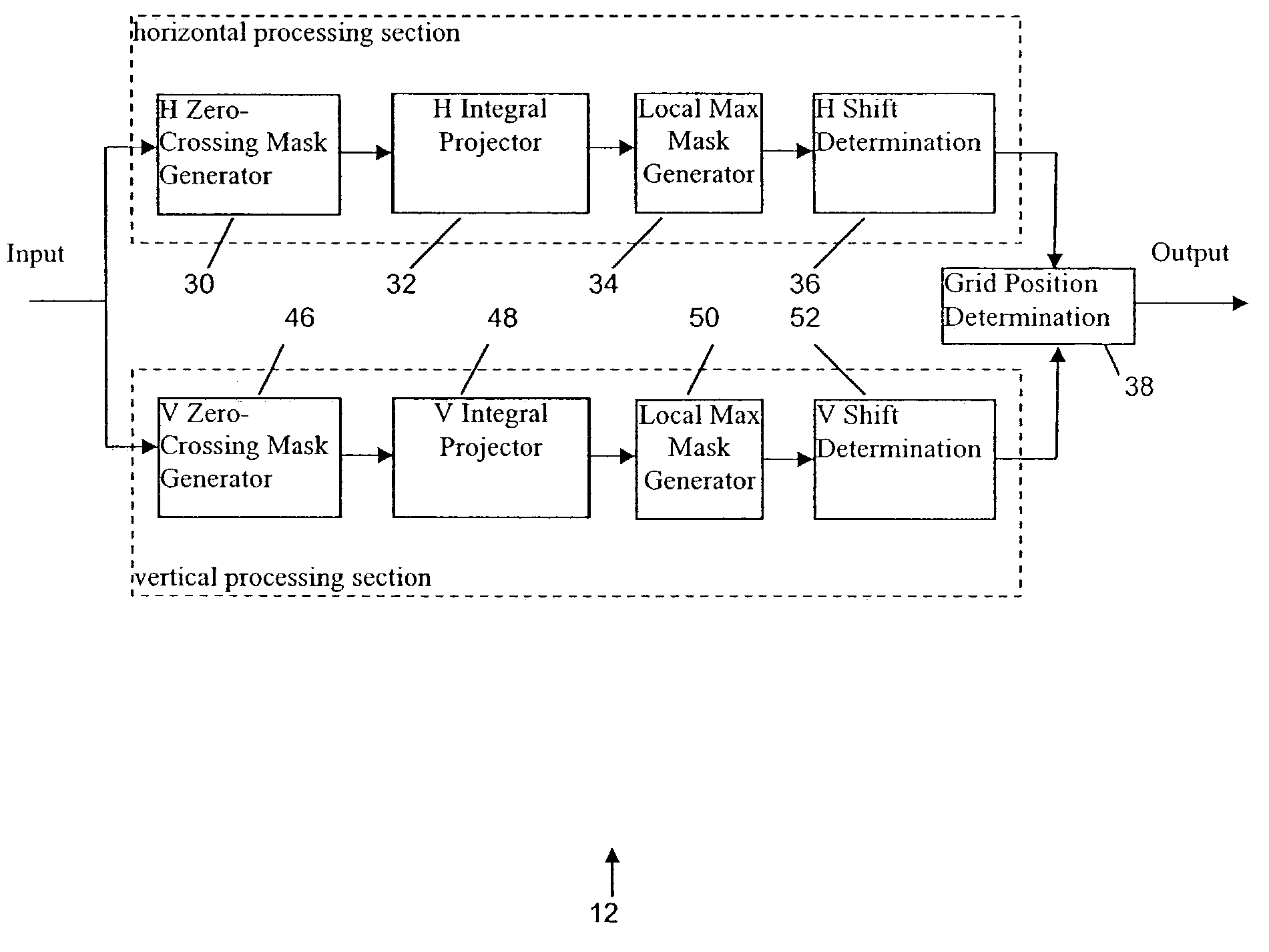
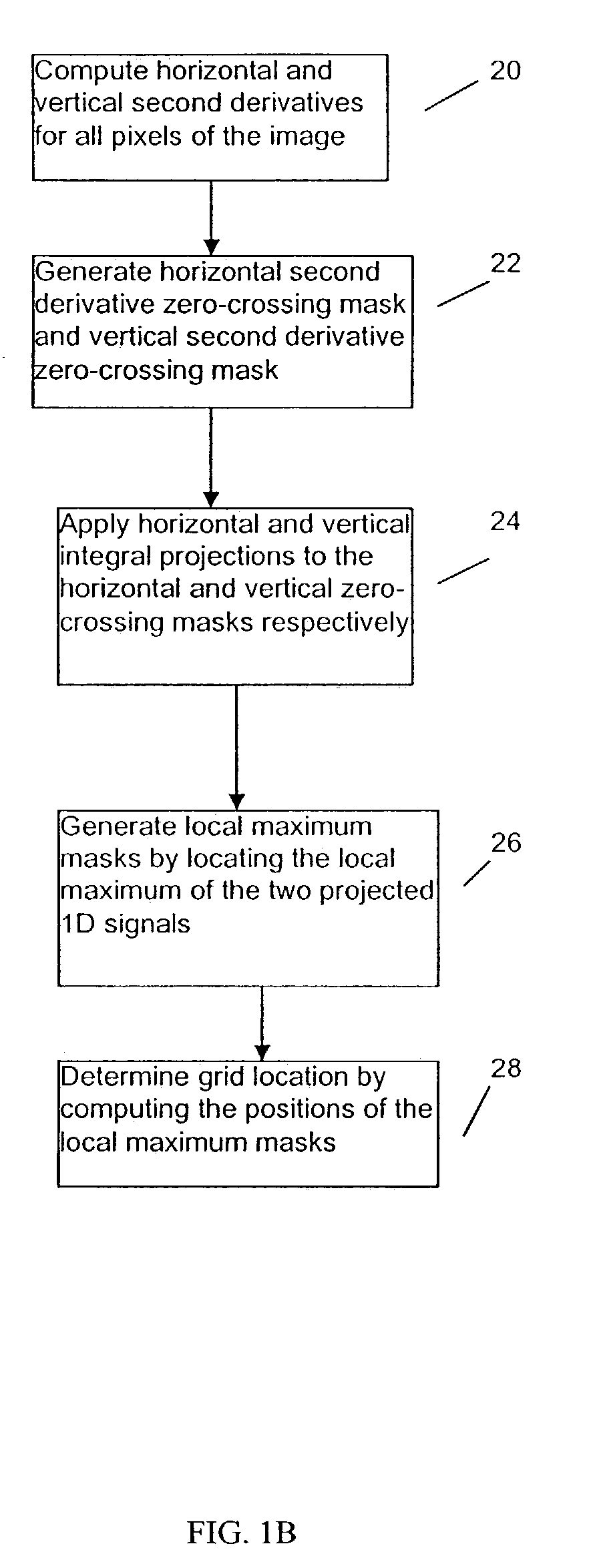
A grid detector detects the existence and the location of grids in DCT compressed videos. When a grid is detected in the input video, a post-processor is turned on and the de-blocking processing is applied on the grid detected by the grid detector. When no grid is detected, indicating that the input video is either an uncompressed video or an already de-blocked video, post-processing turned off to avoid degrading the picture quality. To detect grids, the grid detector: (a) computes horizontal and vertical second derivatives for all pixels of the image; (b) generates horizontal second derivative zero-crossing mask and vertical second derivative zero-crossing mask by marking the those pixels whose second derivatives have opposite signs with respect to their horizontal or vertical neighboring pixels'; (c) applies horizontal and vertical integral projections to the horizontal and vertical zero-crossing masks respectively; (d) generates the local maximum masks by locating the local maximum of the two projected 1-D signals; and (e) determines grid location by computing the positions of the local maximum masks.

Description

FIELD OF THE INVENTION [0001]The present invention relates generally to video signal processing, and more particularly to detecting block grid in block-based compressed video for post-processing.BACKGROUND OF THE INVENTION [0002]Due to simplicity and efficiency, Discrete Cosine Transform (DCT) based compression techniques are dominant in video compression. Many popular video compression standards, such as MPEG-2, MPEG-4 and H.261, employ DCT techniques. The basic approach of a DCT based compression technique is to subdivide the image into 8×8 blocks and then individually transform, quantize, and encode each block. However, this block-based encoding technique introduces blocking artifacts between block boundaries because the DCT does not take the correlation between block boundaries into account. The blocking artifacts are typically the most noticeable picture degradation in DCT based coding systems.[0003]Many post-processing algorithms have been proposed to remove the blocking artif...

Claims


Application Information

Patent Timeline
IPC IPC(8): G06K9/40H04B1/66G06T9/00H04N5/21H04N7/26H04N7/30
CPCH04N19/865H04N19/86H04N5/21C02F3/06C02F3/109C02F2203/006
Inventor LIN, PENGKIM, YEONG-TAEG
Owner SAMSUNG ELECTRONICS CO LTD
Learn More