Handlebar grip, in particular for a bicycle

a technology for bicycles and handles, applied in the field of handles, can solve the problems of not allowing a stable and easy engagement affecting the stability of the functional difficulty of fitting the grip on the handlebar, etc., to achieve the effect of wide tolerance range, easy arranging on the handlebars, and dampening the vibration transmitted from the ground

Inactive Publication Date: 2007-05-22
SELLE ROYAL SPA
View PDF19 Cites 61 Cited by
  • Summary
  • Abstract
  • Description
  • Claims
  • Application Information

AI Technical Summary

Benefits of technology

[0016]A primary object of the present invention is therefore that of eliminating the drawbacks of the abovementioned known art by providing a grip for bicycles which guarantees a stable fixing action on handlebars of differing cross-sections within a sufficiently wide tolerance range.
[0017]A further object of the present invention is that of designing a grip which is particularly resistant in terms of wear phenomena and at the same time sufficiently soft to dampen the vibrations transmitted from the ground.
[0018]Another particular object of the present invention is that of designing a grip which is constructionally simple and operationally completely reliable.
[0019]A further object of the present invention is that of providing a grip which can be easily arranged on the handlebars of any bicycle.
[0020]These objects, together with others, are all achieved by the handlebar grip, in particular for a bicycle or the like, which forms the subject of the present invention and comprises a mai...

Problems solved by technology

Moreover, the same grips made of, or solely lined with, relatively soft materials are more easily subject to wear.
In practice, however, both the embodiments shown in this patent do not allow a stable and easy engagement of the grip on the handlebar.
It should be noted in particular that in the case where the grip is formed completely by material in gel form, it can be functionally difficult to fit the grip on the handlebar, given the significant friction which the gel material exerts on the metallic surface of the handlebar and which must be overcome during said insertion operation.
It is nonetheless clear that, in practice, it is not always possible to guarantee such machining precision and it is therefore convenient to assign the task of retaining the grip on the handlebar to the abovementioned central projection.
In this case, however, the retaining force may be unsat...

Method used


Image

  • Handlebar grip, in particular for a bicycle
  • Handlebar grip, in particular for a bicycle
  • Handlebar grip, in particular for a bicycle

Examples


Embodiment Construction

[0027]With reference to the said drawings, the grip forming the subject of the present invention is labelled in its entirety 1.

[0028]Hereinafter, reference will always be made, for simplicity of explanation, to a grip for bicycles, it being understood that said grip may be used on all types of wheeled vehicles, such as scooters, mopeds, motorcycles, motorbikes or for other types of vehicles using grips.

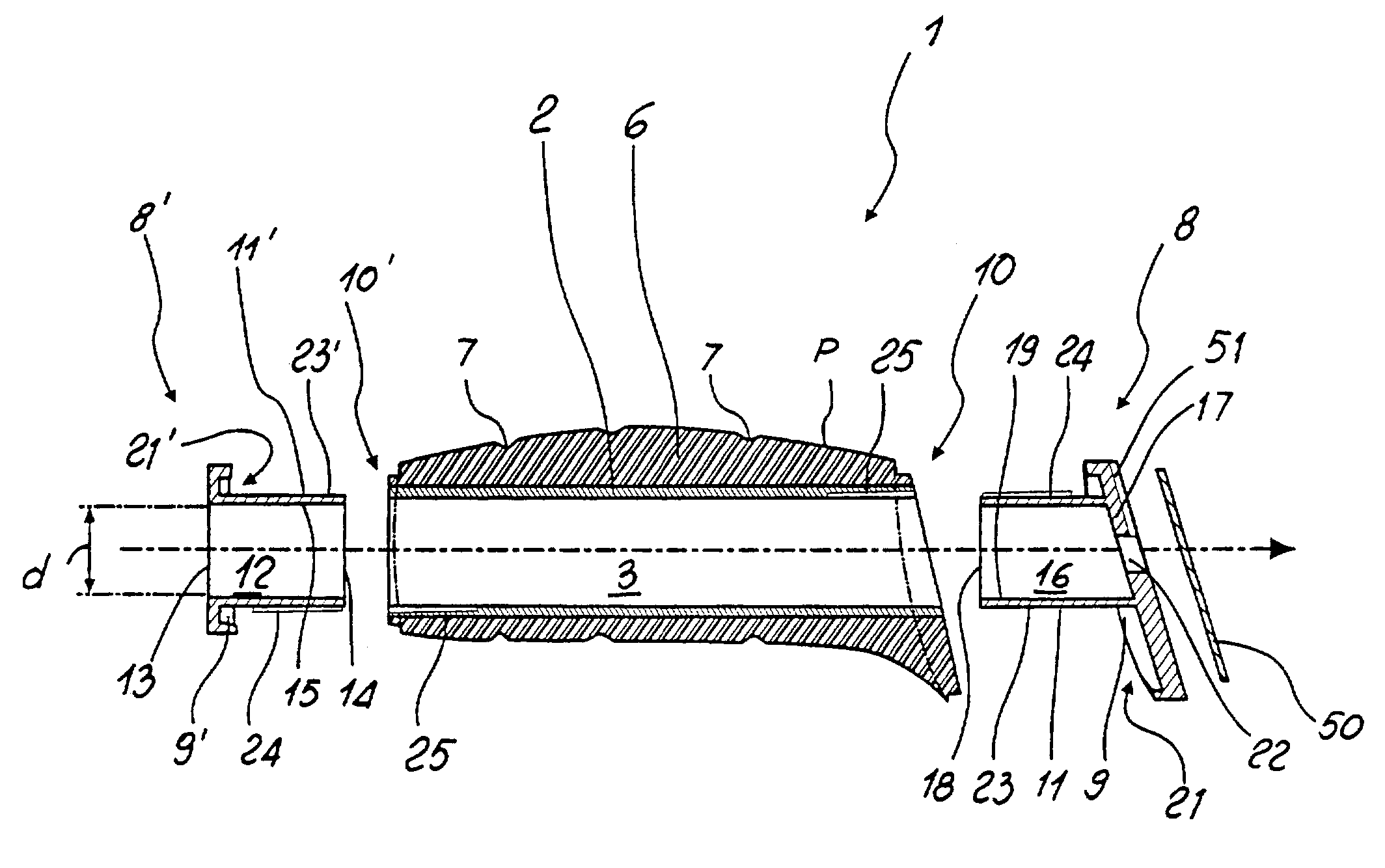
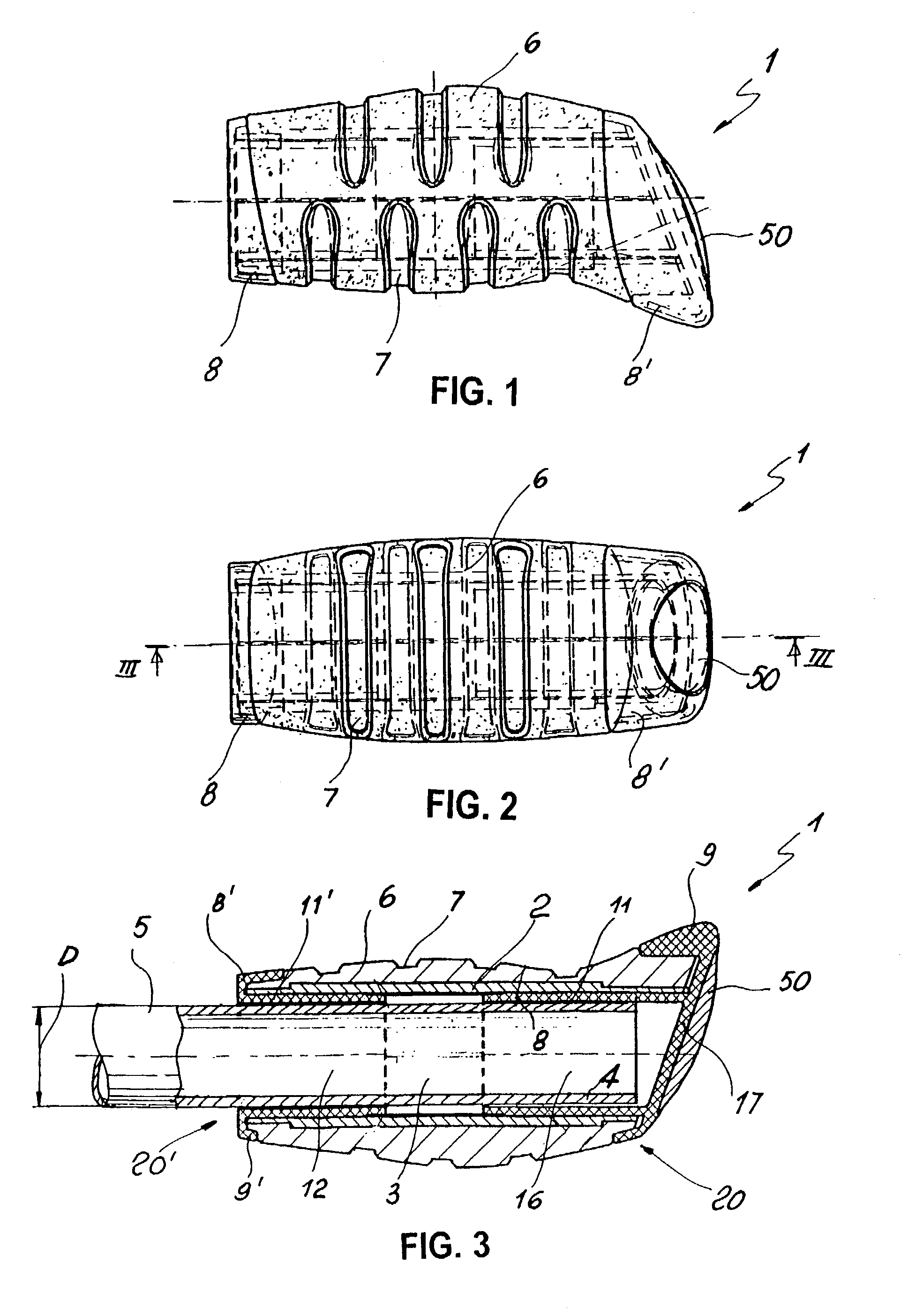
[0029]According to the embodiment indicated in the attached drawings, the grip 1 is substantially formed by a main body 2 made of rigid or semi-rigid material and having a substantially tubular shape with a longitudinal axis A. Said axis defines internally thereof a cylindrical cavity 3 which, as will be better explained hereinafter, can receive the end section 4 of a handlebar 5.

[0030]A covering 6 of relatively soft material consisting, for example, of elastomeric material in gel form is arranged above the main body 2. The covering 6 has a profile P which is suitably shaped so as to ...


PUM


Abstract

Handlebar grip for a bicycle or similar vehicle, formed by a main rigid body of tubular shape supporting, fixed thereon, a covering of moderately soft material, in particular in gel form. Two terminal elements are provided at the ends of the grip, each of the elements being provided with an annular protection rim intended to line a corresponding end edge of the covering, and with an elastically deformable tubular lug to be inserted between an end section of the handlebar and the main body, compressed between the handlebar and the main body so as to ensure gripping engagement as a result of friction thereon.

Description

FIELD OF APPLICATION[0001]The present invention relates to a grip intended to be traditionally mounted on the handlebars of a bicycle or on other vehicles so as to ensure a secure gripping action by cyclists or other users.BACKGROUND ART[0002]As part of the continuous development of improvements made to all the constructional details which compose bicycles, the grip which forms the subject of the present invention arises in response to the need to simplify the manufacturing process and from requirements to improve their qualitative and operational characteristics.[0003]The grips on the market nowadays generally differ from each other in terms of their particular anatomical shape, the materials used or the manufacturing process by means of which they are made.[0004]As is known, said grips are traditionally formed by a substantially cylindrical body which is made of plastic material, is internally hollow and can be inserted onto the ends of handlebars generally formed by suitably shap...

Claims


Application Information

Patent Timeline
IPC IPC(8): B62K21/26B62K21/12
CPCB62K21/26Y10T16/498Y10T16/466Y10T16/469
Inventor BIGOLIN, RICCARDO
Owner SELLE ROYAL SPA
Why Eureka
Try Eureka