
Method of producing bus bars for centralized power distribution unit

a technology of centralized power distribution and bus bars, which is applied in the direction of windings, generators/motors, and applying solid insulation, etc., can solve the problems of increasing the production cost of a centralized power distribution unit, most of the other portions of the metal plate other than the portions stamped out into a ring-like shape become wasted, and achieve the effect of reducing the cost of molds, reducing material costs, and reducing material loss

Inactive Publication Date: 2007-05-22
SUMITOMO WIRING SYST LTD +1
View PDF13 Cites 33 Cited by
  • Summary
  • Abstract
  • Description
  • Claims
  • Application Information

AI Technical Summary

Benefits of technology

This configuration reduces material waste and production costs by allowing for denser placement of bus bars, minimizing the required metal plate size and mold complexity, resulting in a more economical and efficient manufacturing process.

Problems solved by technology

Most of the portions of the metal plate other than the portions which are stamped out into the ring-like shape become wasted.
Therefore, conventionally, as seen from the above, the conductive metal plate 107 includes a very large useless portion and hence is wasteful.
This is a cause of increased production costs of a centralized power distribution unit.

Method used


Image

  • Method of producing bus bars for centralized power distribution unit
  • Method of producing bus bars for centralized power distribution unit
  • Method of producing bus bars for centralized power distribution unit

Examples


Embodiment Construction

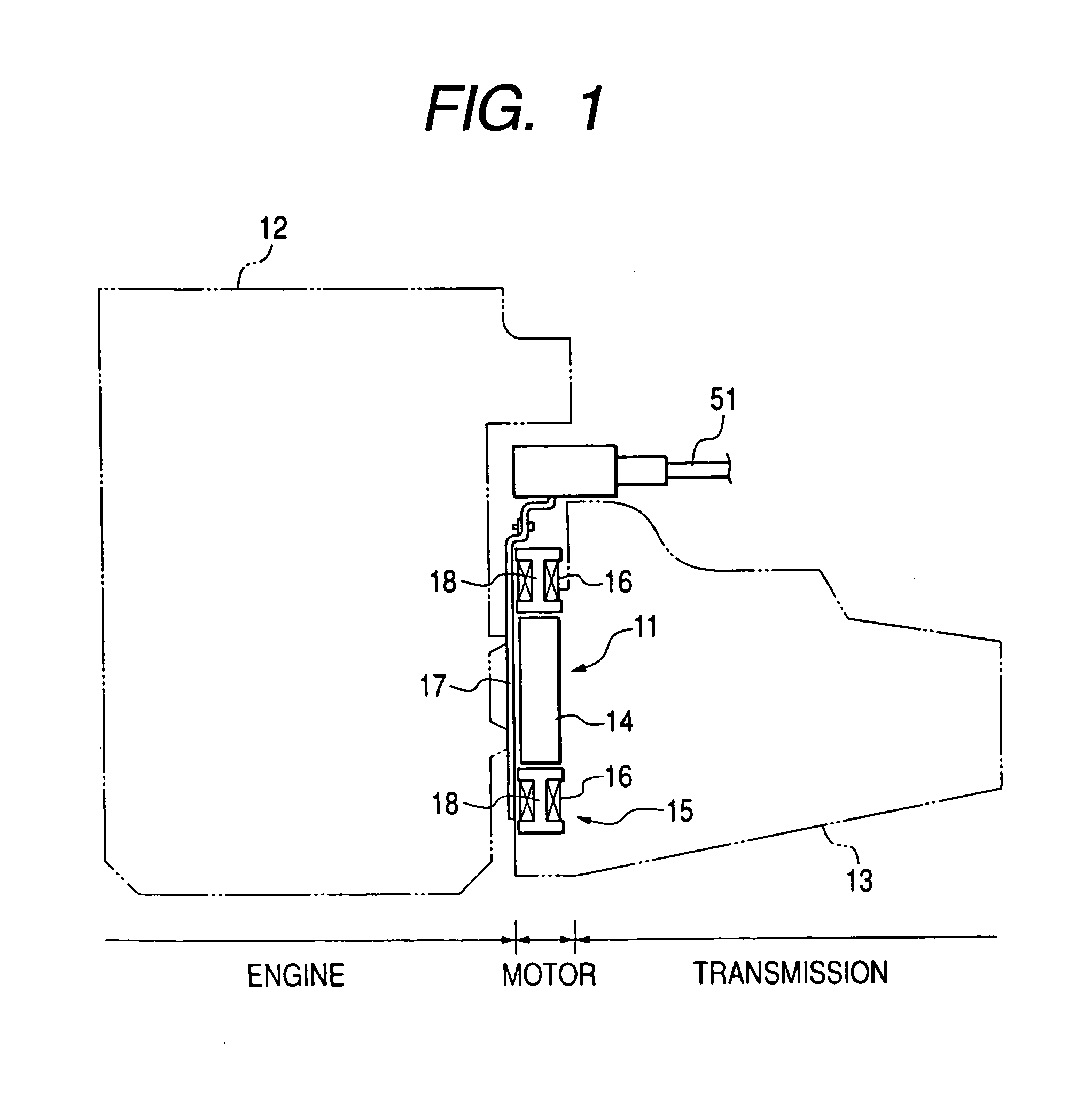
[0068]As shown in FIG. 1, a three-phase thin DC brushless motor 11 to be used in a hybrid automobile is disposed between an engine 12 and a transmission 13. The thin DC brushless motor 11 includes a rotor 14 connected, e.g., directly connected, to a crankshaft of the engine 12, and a ring-like stator 15 enclosing the rotor 14. The stator 15 includes a plurality of magnetic poles that have windings 16 on cores, a stator holder 18 that contains the magnetic poles, and an annular centralized distribution unit 17 that concentratedly distributes currents to the windings 16.

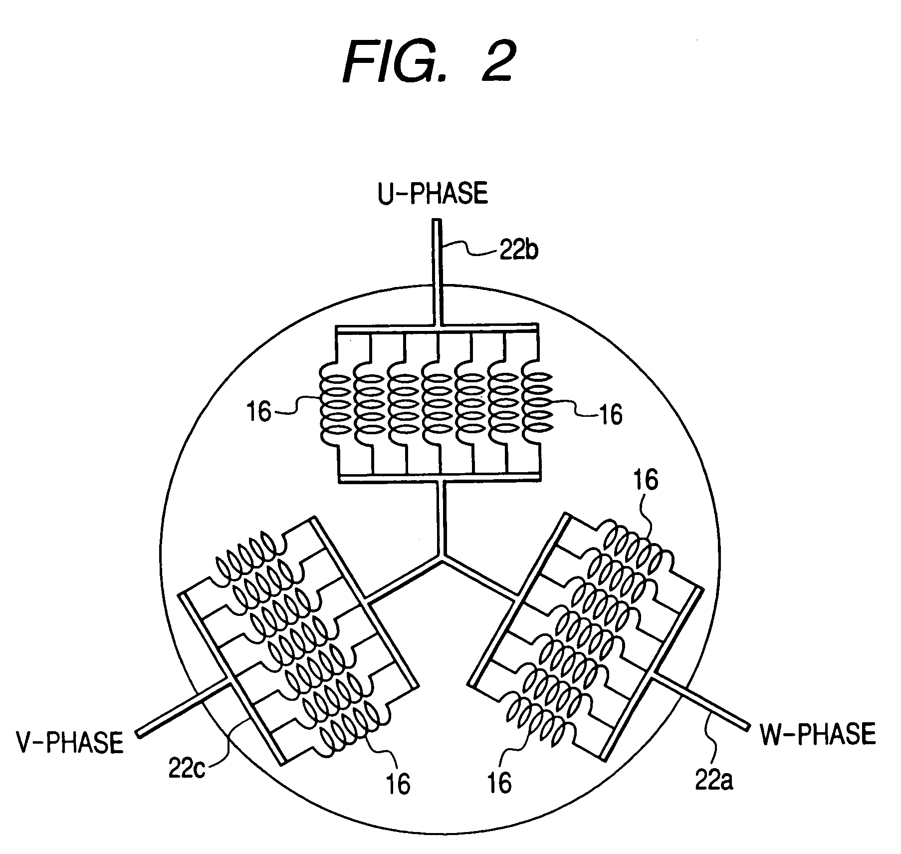
[0069]FIG. 2 shows a schematic diagram of the stator 15. As shown in FIG. 2, an end of each phase winding 16 is connected to one of bus bars 22a, 22b, and 22c formed in the centralized distribution unit 17 while the other end is connected to a ring-like conductive member (not shown).

[0070]As shown in FIGS. 3 to 6, a continuous annular insulating holder 21 (FIGS. 6A and 6B) made of synthetic resin is embedded in the cen...


PUM

PropertyMeasurementUnit
angleaaaaaaaaaa
taper angleaaaaaaaaaa
conductiveaaaaaaaaaa

Abstract

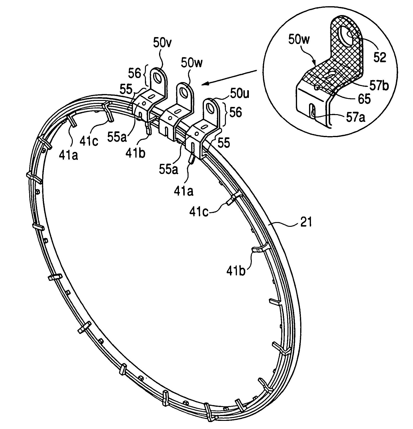
To produce bus bars, a conductive metal plate is stamped out into a plurality of strips simultaneously by press molding. Each strip has a tab having an L-shaped cross-section defined by a curved section and a distal end. The plurality of strips are bent in a thickness direction to obtain a plurality of rings, respectively. The rings are mutually different in diameter and have substantially the same center. The L-shaped tab of each of the rings is disposed such that the distal end of each tab is disposed substantially at a same distance from the center.

Description

CROSS REFERENCE TO RELATED DOCUMENTS[0001]This is a Division of Application Ser. No. 10 / 281,202 filed Oct. 28, 2002, now U.S. Pat. No. 6,894,410, which claims the benefit of Japanese Patent Application No. 2001-330026 filed Oct. 26, 2001. The entire disclosure of the prior application is hereby incorporated by reference herein in its entirety.BACKGROUND OF THE INVENTION[0002]1. Field of Invention[0003]The present invention relates to a centralized power distribution unit which is used for performing centralized power distribution on stator windings of a vehicular thin brushless motor.[0004]2. Description of Related Art[0005]Recently, automobiles with good fuel economy have been in high demand. As one example of automobile manufacturers' efforts to meet these demands, hybrid cars with super low fuel consumption have been developed. In particular, a hybrid car has been proposed recently which is provided with an auxiliary power mechanism (a motor assist mechanism) in which an engine p...

Claims


Application Information

Patent Timeline
Patent Type & Authority Patents(United States)
IPC IPC(8): H01H69/02H02K3/50H02G3/16H02K5/22H02K15/00H02K15/10H02K29/00
CPCH02K15/0056H02K15/0062H02K15/10H02K3/50H02K2203/09Y10T29/49009Y10T29/49105Y10T29/49117Y10T29/49107
Inventor KOBAYASHISUZUKI, IZUMIHORIE, TATSUROFUKUDA, KENJI
Owner SUMITOMO WIRING SYST LTD
Learn More