Internal combustion engine with regenerator, hot air ignition, and naturally aspirated engine control

a technology of internal combustion engine and regenerator, which is applied in the direction of machines/engines, output power, mechanical equipment, etc., can solve the problems of increased exhaust pollution, carnot cycle rule, and lack of efficiency of current internal combustion engine to compete with fuel cells and other alternative vehicle movers, etc., to achieve low heat loss, low flame temperature, and efficient fuel ratio

Inactive Publication Date: 2007-05-22
PATTON RICHARD
View PDF44 Cites 29 Cited by
  • Summary
  • Abstract
  • Description
  • Claims
  • Application Information

AI Technical Summary

Benefits of technology

[0055]The internal combustion engine of the present invention combines the fuel-saving features of a operating over a wide range of conditions within a narrow, efficient fuel ratio, low flame temperature, low heat losses, and high volumetric efficiency by using separate compression and power cylinders connected by a regenerator with a uniflow design so as to enable hot air ignition, and further includes the advantages of improved engine control when the engine is naturally aspirated (NA). Control of the NA engine of the present invention is accomplished through controlled valve timing.
[0057]It is a further object of the invention to provide an internal combustion engine that produces very little pollution.

Problems solved by technology

It is well recognized that the current generation of internal combustion (IC) engines lacks the efficiency needed to compete with fuel cells and other alternative vehicle movers.
The basic cause of the breakdown in the Carnot cycle rule is due to the fact that the properties of air change as the temperature increases.
This dissociation leads to increased exhaust pollution.
1) Intake—Air picks up heat from the intake valve and from the hot head, piston and cylinder. Generally speaking, the air heats up from 100-200 F.
2) Compression—The air continues picking up heat, in addition to the work done on it by the engine.
3) Power—Air is hot after firing, and begins to lose heat to the walls. Luminosity of the diesel combustion process accounts for much of the heat lost. The short cycle time of a high speed Diesel engine holds these heat losses by conduction to a minimum.
4) Exhaust—During the blowdown, heat is transferred to the exhaust valve, and hence to the cylinder head.
Addition of water droplets, of course, is impossible with a Diesel engine.
b) 2H2O≡2H2+O2The production of CO, carbon monoxide, is particularly undesirable, as it is a regulated pollutant.
All of these reactions also reduce the engine efficiency.
In the use of a regenerator, the state of the art is not yet commercially feasible.
In particular, the inventor failed to specify a valve between the power piston and the regenerator.
As the compression cylinder is smaller than the engine cylinder, this will cause a loss of pressure during the transfer process.
In addition, there is no valving controlling the flow of air through the regenerator.
Almost by definition, a high friction engine cannot be efficient.
The current state of the art as commercially practiced does not produce engines that have adequate fuel economy.
The state of the art as practiced in the patent literature does not adequate regulate the air flow through the regenerator.
As these hot gases are expanding, the reduction in volume in this movement causes loss of power and efficiency.
A gas temperature which is too high will melt the components, and also cause problems with NOx control.

Method used


Image

  • Internal combustion engine with regenerator, hot air ignition, and naturally aspirated engine control
  • Internal combustion engine with regenerator, hot air ignition, and naturally aspirated engine control
  • Internal combustion engine with regenerator, hot air ignition, and naturally aspirated engine control

Examples


Embodiment Construction

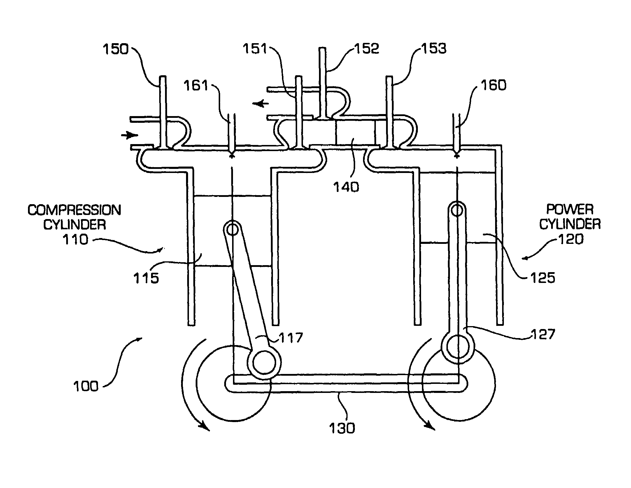
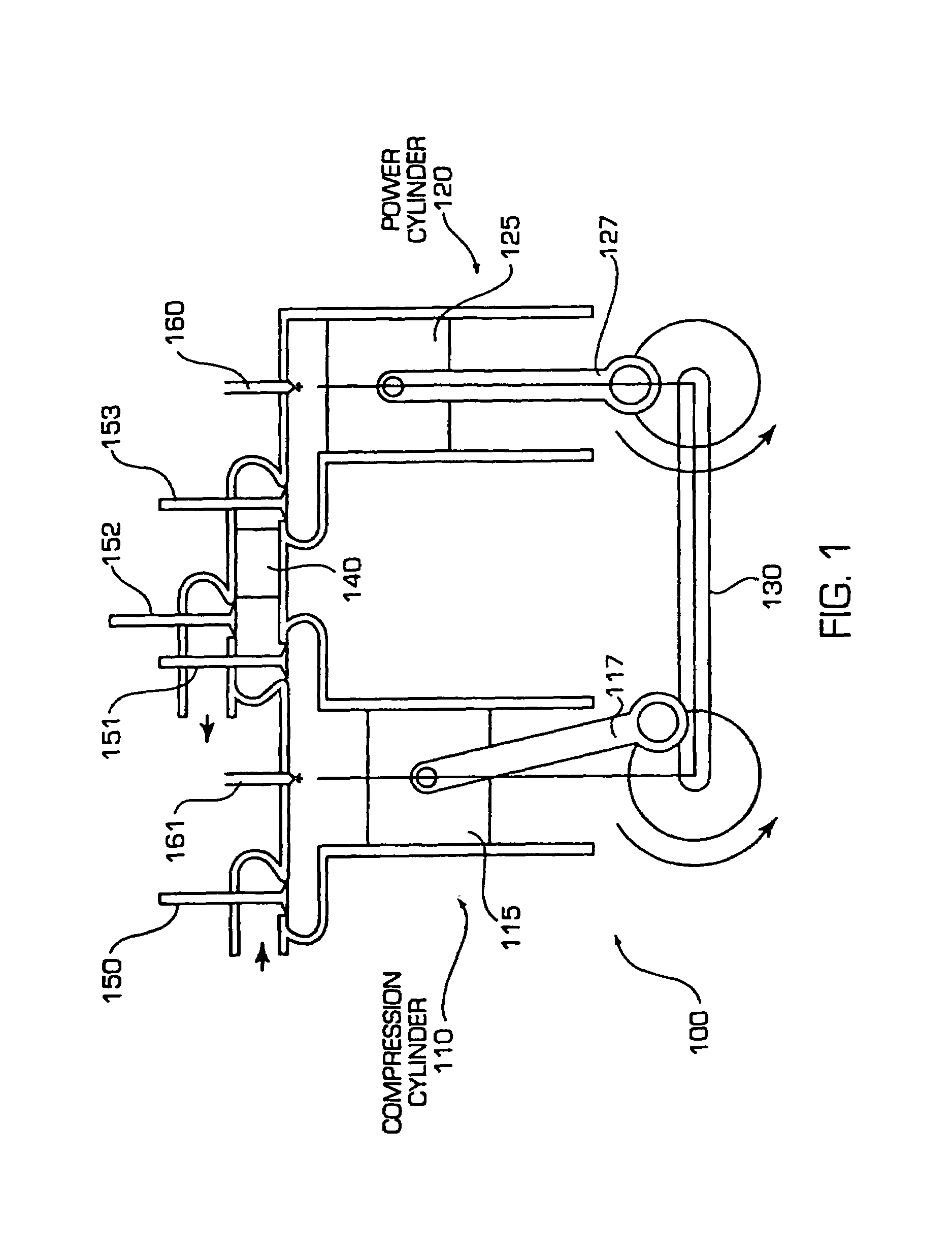
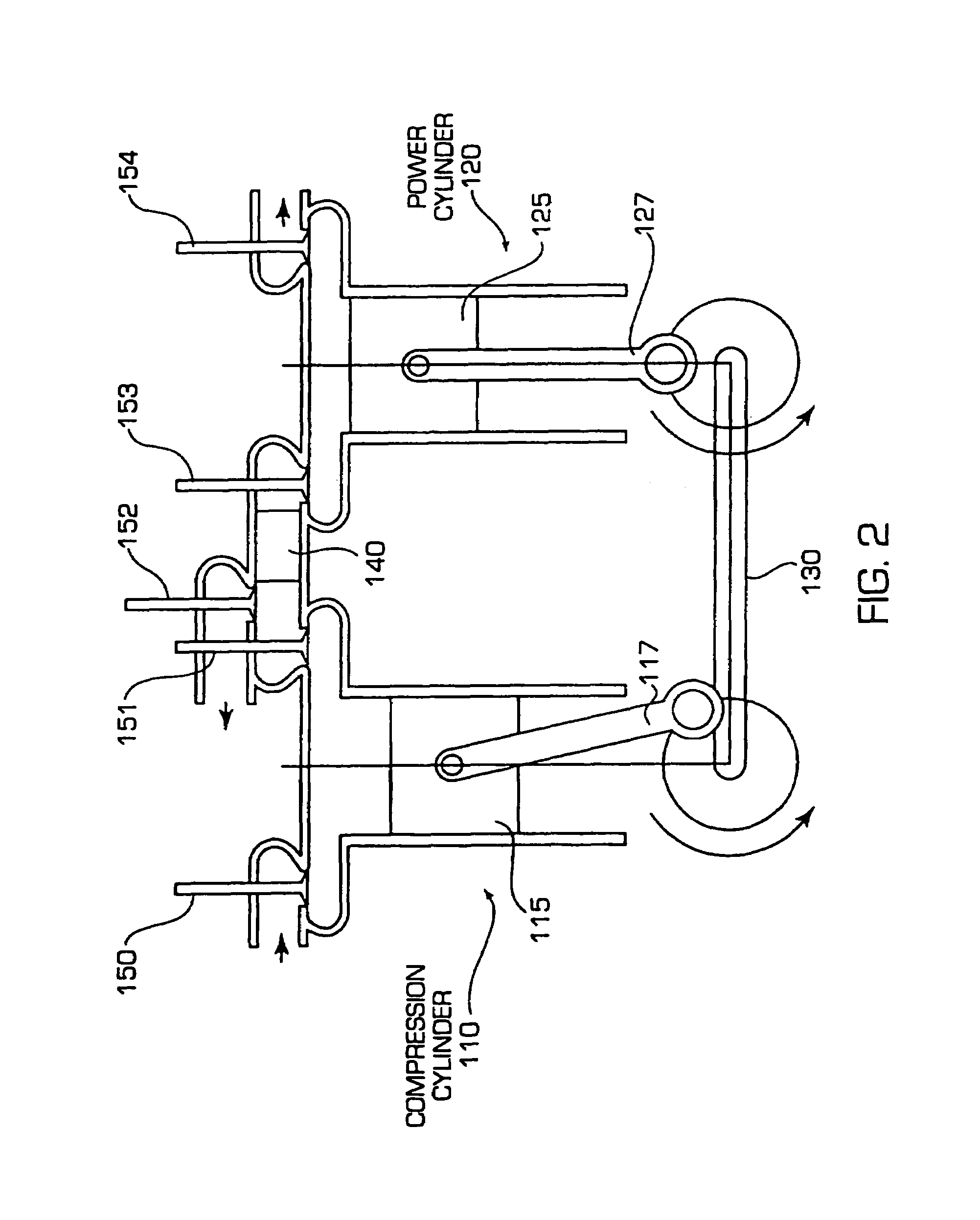
[0081]The engine of the present invention has separate cylinders for intake / compression (compression cylinder) and for power / exhaust (power cylinder). The compression cylinder is cool, and in fact during the intake and compression process, efforts can be made to create a nearly isothermal compression process by optionally adding water droplets to the intake air.

[0082]The power cylinder is the ‘hot’ cylinder, with typical head and piston temperatures in the range of 1000-1100 F. This necessitates the use of 18 / 8 (SAE 300 series) stainless steels for the head and piston, and superalloys for the valves. Combustion temperatures are in the neighborhood of 2000-3000 F. The high heat of the combustion chamber prior to combustion reduces the heat transfer from the working fluid to the chamber during the power stroke. It also reduces the radiant heat transfer, however the larger reduction in radiant heat transfer comes from keeping the maximum temperature below 3000 F.

[0083]The compression a...


PUM


Abstract

An internal combustion engine and method is disclosed wherein separate compression and power cylinders are used and a regenerator or pair of regenerators is mounted between them to provide heat for hot-air ignition. The single regenerator embodiment operates as a two-stroke cycle engine and the embodiment with an alternating pair of regenerators operates as a four-stroke cycle engine. The engine varies the amount of air entering the power cylinder to control the engine output during naturally aspirated operation using valve timing and / or volume control of dead space and can optionally include supercharging to control the engine at higher output levels.

Description

RELATED APPLICATIONS[0001]This application is a continuation in part of application Ser. No. 10 / 638,208 filed Aug. 8, 2003, now U.S. Pat. No. 7,004,115; which is a continuation in part of application Ser. No. 09 / 978,151 filed Oct. 16, 2001, now U.S. Pat. No. 6,606,970, which is a continuation in part of application Ser. No. 09 / 651,482 filed Aug. 30, 2000, now U.S. Pat. No. 6,340,004, which claims the benefit of Provisional Application Ser. No. 60 / 151,994, filed Sep. 1, 1999, all of which are incorporated herein by reference.FIELD OF THE INVENTION[0002]This invention relates to the field of internal combustion engines, and in particular to the control of the regenerative engines disclosed in the present inventor's U.S. Pat. Nos. 6,340,004 and 6,606,970 when the engines are naturally aspirated.BACKGROUND OF THE INVENTION[0003]As discussed in U.S. Pat. No. 6,340,004, the fuel economy of vehicles primarily depends on the efficiency of the mover that drives the vehicle. It is well recogn...

Claims


Application Information

Patent Timeline
Patent Type & Authority Patents(United States)
IPC IPC(8): F01B29/04F02B25/00F02B33/44F02B47/02F02G5/00
CPCF01L1/022F02B33/22F02B37/105F02G5/02F01L1/024F01L1/026F01L1/34F01L2820/01F02B2075/025F02B2075/027F02D13/0203F02D13/028F02M25/03Y02T10/144Y02T10/163Y02T10/166Y02T10/12
Inventor PATTON, RICHARD
Owner PATTON RICHARD
Why Eureka
Try Eureka