Bearing support device

a bearing support and support technology, applied in the direction of bearing unit rigid support, machine/engine, combustion air/fuel air treatment, etc., can solve the problems of abnormal noise generation, lower molding precision, lower productivity and higher costs, etc., to improve slidability, improve reliability, and low molding precision

Inactive Publication Date: 2007-05-22
DENSO CORP
View PDF14 Cites 20 Cited by
  • Summary
  • Abstract
  • Description
  • Claims
  • Application Information

AI Technical Summary

Benefits of technology

[0010]An object of the present invention is to provide a bearing support device which, by simply fitting a bearing member into a fitting hole of a bearing holding member, enables the circularity and concentricity of the bearing hole of the bearing member to be favorably maintained, even in a bearing structure comprising components that are made of resin materials with a comparatively low molding precision, thereby enabling both improved slidability between the rotor and the bearing member, and improved reliability. Another object is to provide a bearing support device which is easier to assemble and enables improved productivity by enabling centering of the bearing hole of the bearing member at the same time that the bearing member is fitted within the fitting hole of the bearing holding member.
[0011]The invention includes a bearing structure in which a rotor and a bearing member are both made of a resin, wherein the components are made of resin materials with a comparatively low level of molding precision. Furthermore, by providing an engagement section, for tightly fitting the bearing member with a bearing hole into a fitting hole of a bearing holding member, in a positional relationship relative to the bearing hole that enables the engagement force produced by the tight fitting to act in a direction that does not affect the inner diameter dimensions of the bearing hole of the bearing member, the circularity and concentricity of the bearing hole of the bearing member can be favorably maintained by simply fitting the bearing member into the fitting hole of a bearing holding member, even in a bearing structure comprising components that are made of resin materials with a comparatively low molding precision, thereby enabling both improved slidability between the rotor and the bearing member, and improved reliability. Furthermore, because the bearing member can be secured and held by simply fitting the bearing member into the fitting hole of the bearing holding member, and using the engagement force produced by the tight fit of the bearing member inside the fitting hole of the bearing holding member, the assembly operation is simple, only a small number of parts is required, and improved productivity and reduced costs can be realized.
[0012]In another aspect of the invention, the engagement section for tightly fitting the bearing member with the bearing hole into the fitting hole of the bearing holding member may be provided in a positional relationship relative to the bearing hole that enables the orientation of the engagement stress, which is generated within the bearing member when the bearing member is fitted tightly into the fitting hole of the bearing holding member, to occur in substantially the circumferential direction of the bearing member, away from the radial inner diameter of the bearing member. In this aspect, as with the aspect above, deterioration in the circularity of the bearing hole of the bearing member, caused by the engagement stress that is generated in the bearing member when the bearing member is fitted tightly into the fitting hole of the bearing holding member, can be prevented. Accordingly, even in a bearing structure comprising components that are made of resin materials with a comparatively low molding precision, the bearing clearance between the inner diameter surface of the bearing member and the outer diameter surface of the rotor can be substantially reduced, and deterioration in the slidability and abrasion resistance between the bearing member and the rotor can be prevented.

Problems solved by technology

However, when the components of the intake system of an engine are made of a resin, the level of molding precision is lower than that observed for metallic materials.
As a result, rocking of the valve shaft 105 accompanying vibration increases, and the collision speed of the valve bearing section 103 with the valve axis 106 increases further, leading to a problem of abnormal noise generation.
However, in this type of a butterfly valve bearing support structure (a related embodiment), the number of components and the number of assembly steps increases, which may result in lower productivity and higher costs.

Method used


Image

  • Bearing support device
  • Bearing support device
  • Bearing support device

Examples


first embodiment

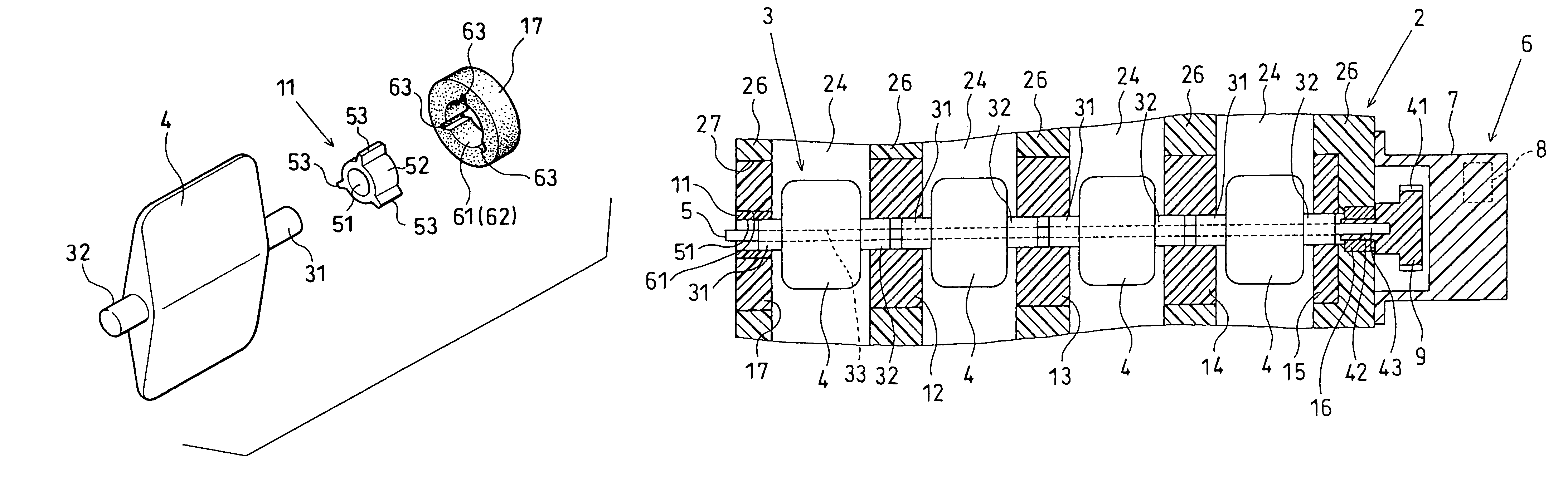
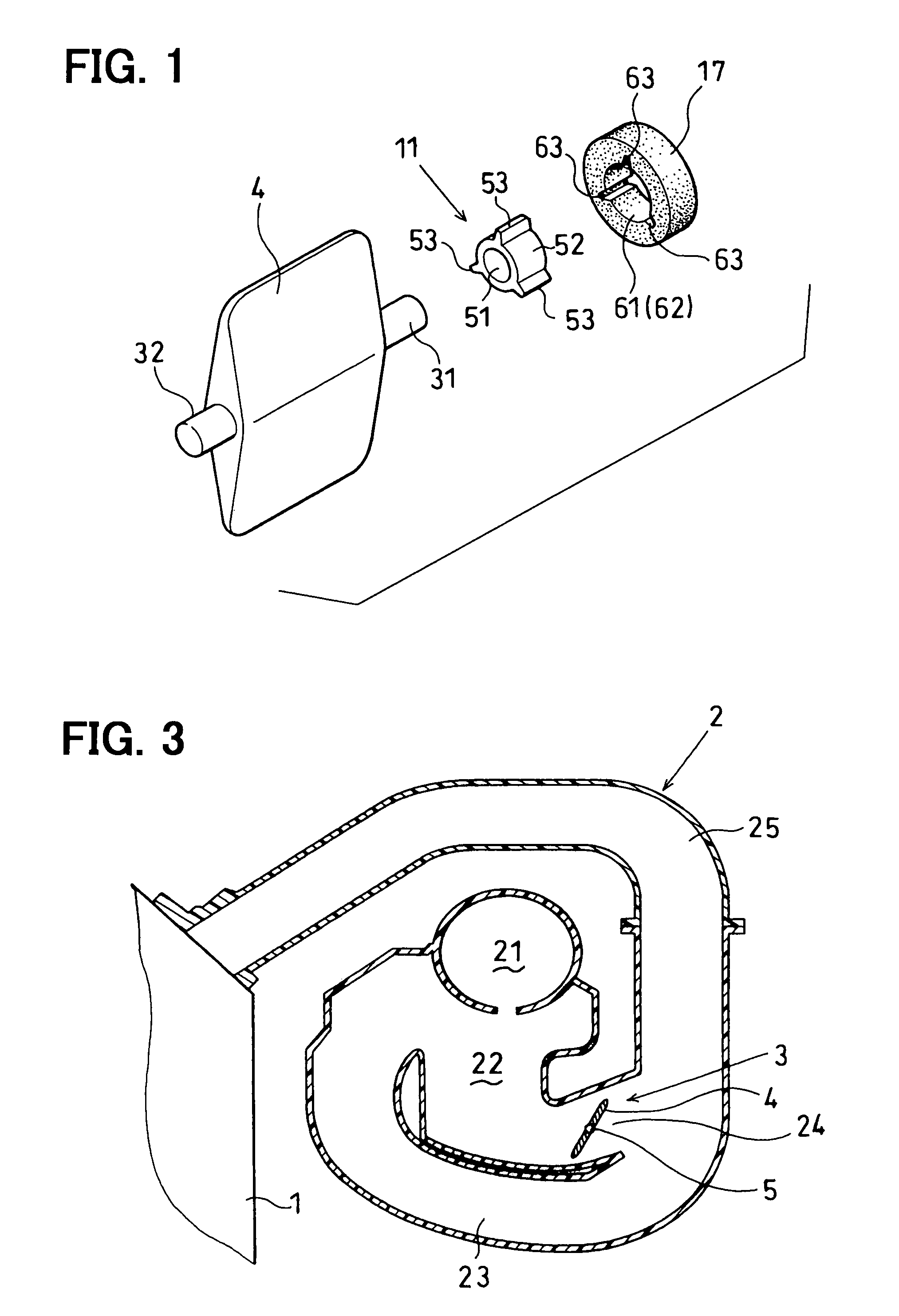
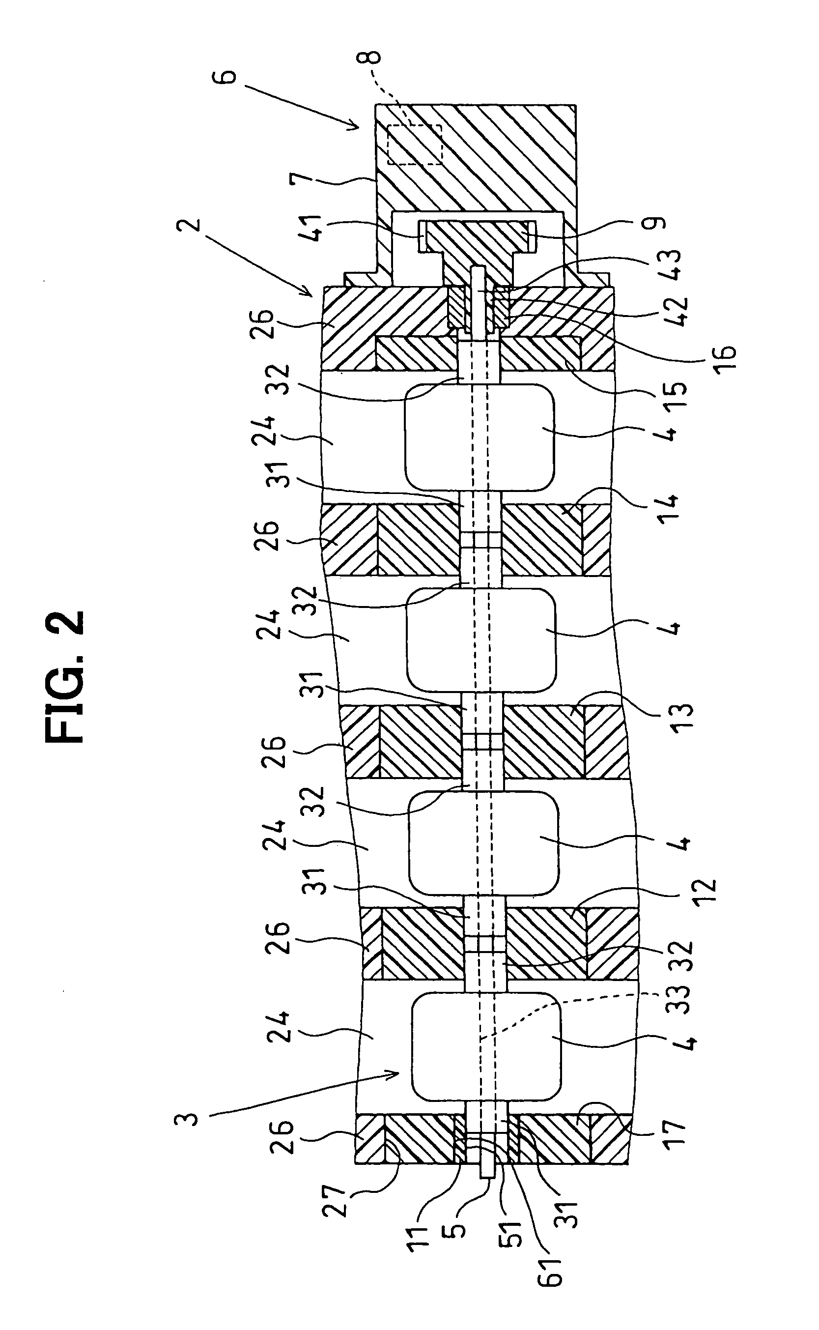
[0039]FIG. 1 through FIG. 5 show the present invention, wherein FIG. 1 shows the construction of a butterfly valve bearing support structure, FIG. 2 shows a variable intake system, and FIG. 3 shows an intake manifold.

[0040]The variable intake system of the present embodiment is provided in an intake system of an internal combustion engine (hereafter, referred to as an engine) 1, such as a multiple (in this case four) cylinder gasoline engine, installed in a vehicle such as an automobile, and comprises a butterfly valve bearing support device, which is provided on the resin intake manifold 2, and supports the rotor (butterfly valve assembly) 3 in a freely rotatable manner via first through fifth valve bearing members (11 through 15) described below. Here, the intake manifold 2 of the engine 1 of the present embodiment distributes and supplies the intake air entering the intake manifold 2 to the intake ports (not shown in the diagrams) provided in each cylinder of the engine 1. This i...

second embodiment

[0070]FIG. 6 shows the present invention including the engagement section for tightly fitting the engagement protrusions 53 of the first valve bearing member 11 into the engagement depressions 63 of the fitting hole 61 of the bearing holding member 17.

[0071]As shown in FIG. 6, in the butterfly valve bearing support structure used in the variable intake system of this embodiment, the plurality of engagement protrusions 53, which are formed so as to protrude radially outward from the outer diameter surface of the valve bearing section 52 of the first valve bearing member 11, each comprise a hemispherical surface and a circular cylindrical shape. Furthermore, two hemispherical protrusions 64, which hold the cylindrical shaped section of one of the plurality of engagement protrusions 53 in a secure manner via point contact or line contact, are provided on the inner wall surface of each of the plurality of engagement depressions 63, which are formed so as to protrude radially outward fro...

third embodiment

[0072]FIGS. 7 and 8 show a butterfly valve bearing support structure used in the variable intake system of a third embodiment including the plurality of engagement protrusions 53 formed so as to protrude radially outward from the outer diameter surface of the valve bearing section 52 of the first valve bearing member 11 are each formed in an approximately truncated triangular shape (a tapered shape) that tapers towards the direction of insertion of the first valve bearing member 11 into the fitting hole 61 of the bearing holding member 17. Furthermore, the plurality of engagement depressions 63, which are formed so as to protrude radially outward from the inner diameter surface of the engagement hole section 62 of the fitting hole 61 of the bearing holding member 17, are formed in an approximately truncated triangular shape (tapered shape) that taper from an opening positioned at one end face of the bearing holding member 17 (the left end face in FIG. 1) towards an opening positione...


PUM


Abstract

A bearing support device includes a rotor, a bearing member, and a bearing holding member. The rotor rotates about a rotation center axis. The bearing member rotatably supports the rotor within a bearing hole passing through the bearing member. The bearing holding member holds the bearing member in a secure manner within a fitting hole that passes through the bearing holding member along the center axis of the rotor via an engagement force produced by tightly fitting the bearing member. The rotor and bearing member are made of a resin. An engagement section is provided for tightly fitting the bearing member into the fitting hole relative to the bearing hole to enable an engagement force produced by the tight fitting to act in a direction that does not affect an inner diameter dimension of the bearing hole.

Description

CROSS REFERENCE TO RELATED APPLICATIONS[0001]This application is based upon and claims the benefit of priority of Japanese Patent Application No. 2004-56718, filed on Mar. 1, 2004, the contents of which are incorporated herein by reference.FIELD OF THE INVENTION[0002]The present invention relates to a bearing support device for supporting a rotor in a freely rotatable manner and, more particularly, to a valve bearing support device for supporting multiple integrated butterfly valves that alter the length or cross-sectional area of intake air passages formed within a resin intake manifold of an engine mounted in a vehicle.BACKGROUND OF THE INVENTION[0003]Conventionally, variable intake systems include technology for switching the length or cross-sectional area of an intake pipe of a multiple cylinder engine between two stages according to factors such as the engine speed and the engine load. The systems apply an inertia supercharging effect or resonance supercharging effect to the in...

Claims


Application Information

Patent Timeline
Patent Type & Authority Patents(United States)
IPC IPC(8): F02D9/08F16K1/02F02D9/10F02B27/00F02B27/02F02B31/00F02D9/02F02M35/104F16C23/04F16C33/20F16C35/067
CPCF02B27/02F02B27/0263F02D9/106F02D9/1095Y02T10/146F02B27/0215F02B27/0273Y02T10/12
Inventor INO, MASAOHAYASHI, TOSHIOYAMANAKA, TETSUJI
Owner DENSO CORP
Why Eureka
Try Eureka