Tap assembly for a liquid vessel having an overfill protection device and a float controlled magnetic level gauge

a technology of overfill protection device and liquid vessel, which is applied in the direction of engine lubrication, liquid/fluent solid measurement, valve type, etc., can solve the problems of unsuitable use of known level gauges with taps, unsuitable and undesirable use of level gauges through vessel openings. , to achieve the effect of compact overall assembly and less spa

Inactive Publication Date: 2007-05-22
TORRENT TRADING
View PDF24 Cites 42 Cited by
  • Summary
  • Abstract
  • Description
  • Claims
  • Application Information

AI Technical Summary

Benefits of technology

[0020]Accordingly, there is provided a tap assembly having a mechanical or magnetic level gauge. A single pivotable float actuates the stem of the overfill protection device as well as the rod of the level gauge. No gear mechanism is used to rotate the rod of the level gauge. The rod of the level gauge can be longitudinally shifted by a simple crank mechanism or cam surface thereby requiring less space than a gear assembly for rotating the rod to permit a compact construction of the overall assembly and to allow for insertion into the vessel through a small vessel access opening. The rod of the level gauge has at an upper end portion thereof received in the tap body a permanent magnet that is axially movable with the rod to actuate by magnetic force a pointer member of an indicator device adapted to be mounted on the tap body. The indicator device is mounted on a side of the tap body and the pointer of the indicator device is rotatable about an axis extending normally or obliquely with respect to the longitudinal axis of the upper end portion of the actuating rod and preferably crossing the longitudinal axis of the upper end portion of the actuating rod in laterally spaced relationship. Preferably, the indicator device is a clip-on indicator device.

Problems solved by technology

This known level gauge is not appropriate for use with a tap provided with an overfill protection device.
The overfill protection device is dimensioned to fit snuggly through an opening of the vessel and if a level gauge of the type disclosed in WO 00 / 02015 is added to the assembly of the overfill protection device, the level gauge would no longer be insertable through the vessel opening, unless the diameter of the opening is increased, which is undesirable.
Of course, a second opening could be formed in the vessel for a separate level gauge, but providing a second opening in the vessel is also undesirable.

Method used


Image

  • Tap assembly for a liquid vessel having an overfill protection device and a float controlled magnetic level gauge
  • Tap assembly for a liquid vessel having an overfill protection device and a float controlled magnetic level gauge
  • Tap assembly for a liquid vessel having an overfill protection device and a float controlled magnetic level gauge

Examples


Embodiment Construction

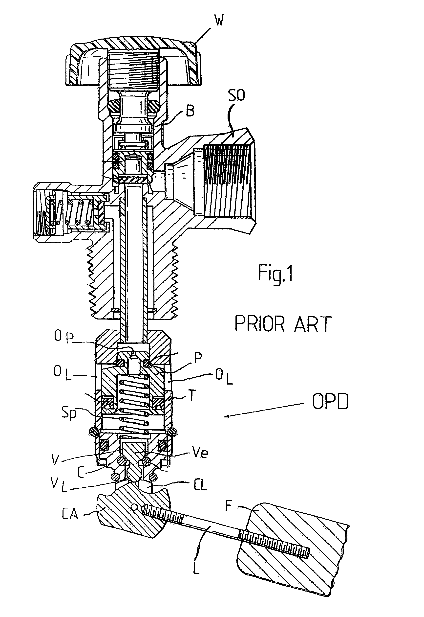
[0052]Referring first to FIG. 1 which shows a prior art tap for a liquefied gas cylinder having an overfill protection device (OPD) disposed below and fixed to the tap body B. The OPD comprises a piston member P axially movable in a tubular member T between an open and a closed position. A pilot valve V is disposed within a closure member C received within the lower end of the tubular member T. A pivotable float F is mounted on a lever L fixed to a cam member CA that is pivotably mounted between two clevis arms CL provided at the lower end of the closure member C. The pilot valve V has a valve element Ve having a lower appendage VL cooperating with a cam surface of the cam member CA. A spring Sp is arranged between the closure member C and the piston member P and forces the piston member P towards its closed position.

[0053]A hand wheel W is mounted on the tap body B for opening and closing the tap to permit filling of gas into a gas cylinder on which the tap is mounted or to dischar...


PUM


Abstract

This invention relates to a tap assembly for a liquid vessel, having an overfill protection device and a float controlled mechanical or magnetic level gauge. A single float actuates a stem of the overfill protection device as well as a rod of the level gauge. The rod of the level gauge has one end movable linearly in a valve body bore and carrying a permanent magnet for actuating a magnetic level indicator. In one embodiment a crank mechanism may be provided between a float lever and the rod of the level gauge to cause the rod to effectuate a swinging movement and simultaneously displace the rod longitudinally to cause linear displacement of the permanent magnet in the valve body bore. In another embodiment the rod may be actuated by a cam to cause axial displacement thereof without swinging motion.

Description

CROSS-REFERENCE TO RELATED APPLICATIONS[0001]Not Applicable.STATEMENT REGARDING FEDERALLY SPONSORED RESEARCH OR DEVELOPMENT[0002]Not Applicable.BACKGROUND OF THE INVENTION[0003]The present invention relates to a tap assembly for a liquid vessel, especially for a cylinder for pressurized liquefied gas, having an overfill protection device (OPD) to prevent overfilling of the vessel or gas cylinder, as well as a float controlled level gauge for detecting and indicating the level of the fluid or liquefied gas remaining in the vessel or gas cylinder.[0004]A tap for a gas cylinder having an overfill protection device is disclosed for example in U.S. Pat. No. 5,487,404 issued on Jan. 30, 1996 to Leon Kerger and also in U.S. Pat. No. 6,640,829 issued on Nov. 4, 2003 to Loll Kerger, both of which are incorporated herein by reference. Mounted below the body of the gas tap is an overfill protection device (OPD) having a valve element movable into an open position by the liquefied gas to be fil...

Claims


Application Information

Patent Timeline
Patent Type & Authority Patents(United States)
IPC IPC(8): F16K31/18
CPCF16K1/305F16K1/306F16K1/307F16K21/18F16K31/20F16K31/383F17C2250/0413Y10T137/7371Y10T137/7465Y10T137/8342
Inventor SCHMITZ, JEAN-CLAUDERODERES, PRIVAT
Owner TORRENT TRADING
Why Eureka
Try Eureka