Milling machine as well as method for working ground surfaces

a technology of grinding machine and working surface, which is applied in cutting machines, open-pit mining, maintenance and safety accessories, etc., can solve the problems of short service life of ventilators, requiring considerable additional equipment of machines, and requiring a considerable increase in equipmen

Active Publication Date: 2007-05-22
WIRTGEN GMBH
View PDF5 Cites 25 Cited by
  • Summary
  • Abstract
  • Description
  • Claims
  • Application Information

AI Technical Summary

Benefits of technology

[0011]The invention enables a simple design which does not require the setup of a road milling machine to be basically modified, so that existing road milling machines can also be retrofitted. Given that the suction ventilator of the suction device is arranged behind the separator device, the suction ventilator is operated on the pure-air side, so that the suction ventilator has a longer service life. The invention enables not only a significantly longer service life of the suction ventilator, but also a significant improvement of the air quality in the vicinity of the operator's platform. The pure air is blown off directly into the open. By separating the solids by means of the separator device, the percentage of respirable dusts is reduced to a considerable extent, so that the workplace conditions are considerably improved. The separated solids can be disposed of either onto the transport device in the forward channel section or into a collecting device.
[0013]It is preferably provided that the separator device consists of a filtering device and that the filter cake forming in the filtering device can be disposed of onto the transport device in the forward channel section or into the collecting device. The use of a filtering device has the advantage that it provides a high efficiency with regard to the respirable dusts and that the separated solids can be compacted to a filter cake which can be disposed of more easily without dusts being able to develop again to a considerable extent during the disposal. In principle, it is also possible to compact the filter cake even further with binding agents, for instance, a hydrous mist so that no dusts at all can develop during the disposal.
[0016]One preferred embodiment provides that the forward channel section is separated from the rear channel section by means of separating media in order to largely block any air current without impeding the transport of the milled material. By separating the channel into a forward and a rear channel section, it is ensured that the dust-laden air, which is sucked off via the suction channel in the direction of the material transport, is sucked off from the rear dust-laden channel section only and that no air current can arise in the forward channel section against the direction of the material transport. The division is effected by means of separating media which, on the one hand, do not impede the transport of the milled material and, on the other hand, prevent an air current against the direction of the material transport.
[0017]It is preferably intended that the transport device shows at least one transport conveyor with a conveyor belt and that sealing media for the channel consist of hoods sealing against the conveyor belt and against the housing of the transport conveyor. Together with the conveyor belt and together with the housing of the transport conveyor respectively, the hoods thus form an enclosed channel so that the milled material passes through the transport device entirely enclosed in its circumference. In this way, no dusts or vapors can escape along the channel to the outside. Minor gaps in the course of the channel are irrelevant, because the channel is under negative pressure so that polluted air cannot escape at possible leaks but, at the most, air is sucked in.

Problems solved by technology

Here, it is of disadvantage that an extraction by suction at the transport conveyors takes place against the direction of transport.
The dust-laden air is thereby sucked off towards the rear in the direction of travel and against the actual direction of the material transport, thus requiring a considerable additional expenditure for the equipment of the machine and a distinctly higher ventilator output.
In addition, the ventilator transports the dust-laden air so that high wear and tear leads to a short service life of the ventilator.
According to the prior art, the suction device shows an axial-flow fan arranged in a suction channel which, due to the high exposure to dusts and sharp-edged particles, is subject to heavy wear and tear, which ultimately leads to a reduced air output and the development of bearing damages.
The fan blades of the axial-flow fan are heavily worn and damaged due to the impact and the deflection of the particles being conveyed at high speed.
When larger particles and smaller stones are sucked in, other parts of the ventilator are also damaged mechanically, which in case of a damage to the fan blades frequently results in the occurrence of unbalances leading to bearing damages in continued operation.
In case of repair, it is of disadvantage that the ventilator is arranged at a position which is difficult to access and a repair therefore leads to a major break in operation.
A further disadvantage is that although the dusts are blown off at a distant position in relation to the operator's platform, they are still blown off into the environment so that a pollution of the workplace with dusts and vapors in the vicinity of the operator's platform, even if reduced, still exists.

Method used


Image

  • Milling machine as well as method for working ground surfaces
  • Milling machine as well as method for working ground surfaces
  • Milling machine as well as method for working ground surfaces

Examples


Embodiment Construction

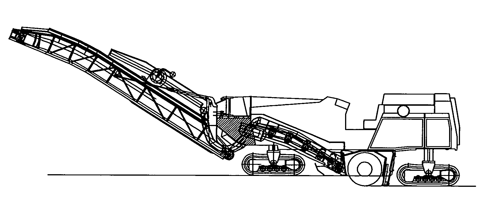
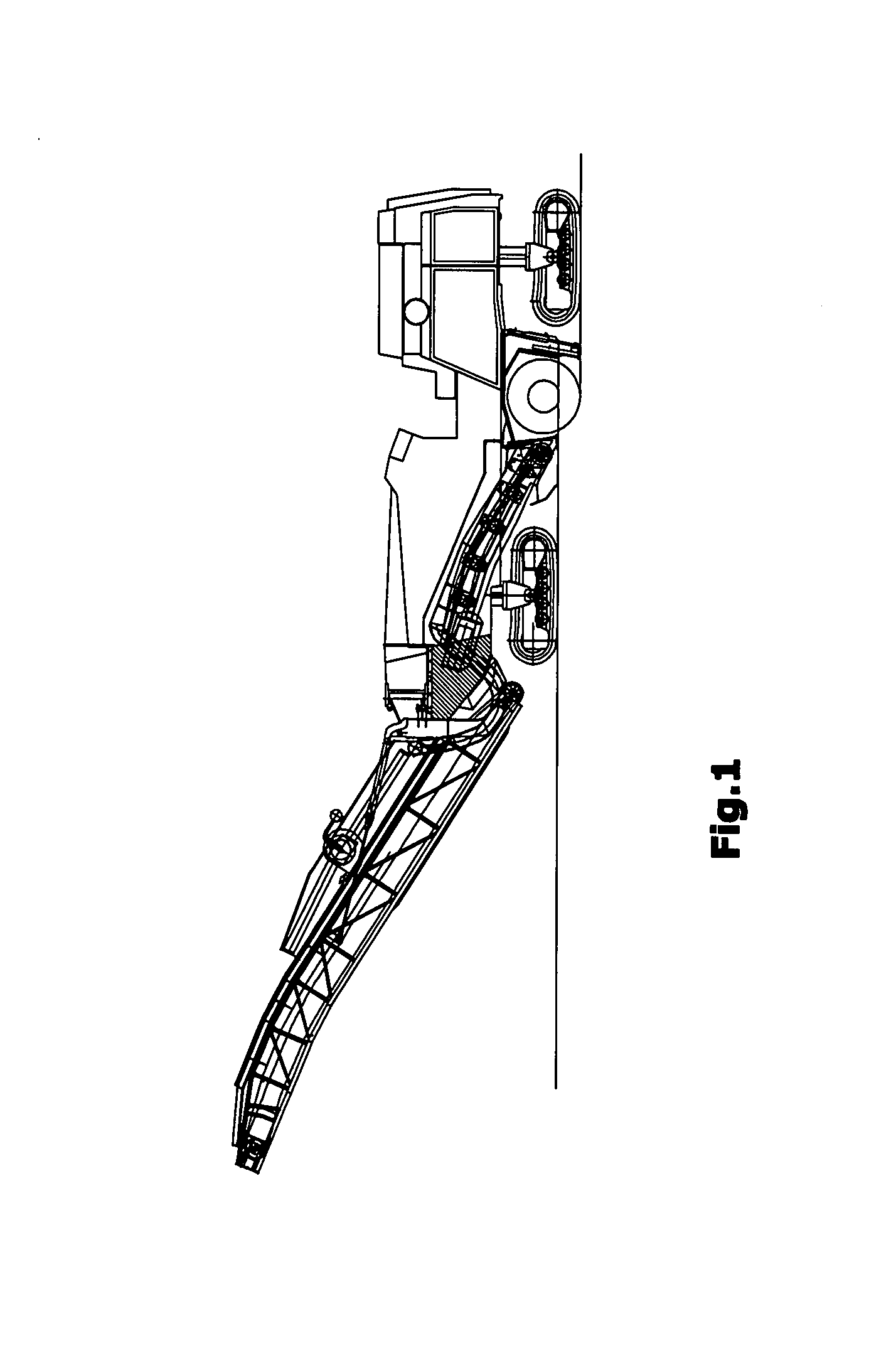
[0029]A road milling machine 1 to work pavements is shown in FIG. 1 in the embodiment of a front-loading road milling machine. It is understood that the invention is also applicable to different milling machines that are provided with at least one transport device 14, 18.

[0030]The road milling machine 1 serves to mill off ground surfaces, in particular pavements made of asphalt, concrete or the like. The road milling machine 1 shows a chassis with, for example, four crawler track units 4 which carries the machine frame 2. It is understood that the crawler track units may be substituted wholly or in part by wheeled units. A milling drum 8, which extends transversely to the direction of travel, is supported in the machine frame 2. The milling depth is preferably set by means of the height adjustment of the crawler track units 4. The road milling machine 1 depicted in FIG. 1 is also referred to as front-loading road milling machine, since it conveys the milled material to the front in ...


PUM

PropertyMeasurementUnit
pressureaaaaaaaaaa
elasticaaaaaaaaaa
flexibleaaaaaaaaaa

Abstract

At a milling machine to work ground surfaces, with a machine frame, a milling drum supported at the machine frame, at least one transport device arranged at the machine frame which accepts the milled material from the milling drum, as well as with a suction device for the air polluted with dusts and vapors, whereby the milled material on the at least one transport device is enclosed by a channel, the suction device is connected to a rear channel section of the channel in the direction of the material transport and sucks off the air polluted during milling at the milling drum and in the rear channel section essentially in the direction of the material transport, it is provided that the suction device consists of a suction ventilator, a separator device for solids and a suction channel which is connected to the rear channel section, that the suction ventilator is arranged downstream of the separator device, and that the suction device disposes of the separated solids onto the transport device in a forward channel section in the direction of the material transport or into a collecting device, and the suction ventilator blows off the cleaned air into the environment.

Description

BACKGROUND OF THE INVENTION[0001]The invention concerns a milling machine to work ground surfaces, in particular pavements, as well as a process to dispose of dusts and vapors developing during the milling operation on a milling machine.[0002]Such milling machines are self-propelled and are also referred to as road milling machines.[0003]A front-loading milling machine in accordance is known from DE 102 23 819 A1. The known road milling machines show a self-propelled chassis with a travel drive unit consisting of several wheel units or several crawler track units. The chassis carries a machine frame in which a milling drum is supported transversely to the direction of travel. To achieve the completest possible removal of the milled material, the milling drum is generally enclosed by a housing, the wall of which pointing in the direction of travel is designed as a covering blade with an opening for the milled material. The material processed by the milling drum is accepted by a first...

Claims


Application Information

Patent Timeline
Patent Type & Authority Patents(United States)
IPC IPC(8): E01C23/088B23Q11/00B28D7/02
CPCB28D7/02E01C23/088E01C2301/50
Inventor BERNING, CHRISTIANLANGE, HERBERTSIMONS, DIETER
Owner WIRTGEN GMBH
Why Eureka
Try Eureka