Cutting insert for high feed face milling

a cutting insert and high feed face technology, applied in shaping cutters, manufacturing tools, transportation and packaging, etc., can solve the problems of large inserts, difficult to fully utilize the advantages provided by round-shaped inserts of increasingly larger radius in conventional machining applications, and increase the rate of material removal, reduce radial cutting forces, and increase feed rates

Inactive Publication Date: 2007-05-22
KENNAMETAL INC
View PDF21 Cites 78 Cited by
  • Summary
  • Abstract
  • Description
  • Claims
  • Application Information

AI Technical Summary

Benefits of technology

[0011]Embodiments of the cutting insert according to the present disclosure may be produced in the form of, for example, face milling inserts. Relative to conventional cutting inserts having linear cutting edges, embodiments of the cutting inserts according to the present invention may allow significantly increased feed rates, reduced radial cutting forces, increase rates of material removal and increased cutting insert life. Embodiments of the cutting insert may be robustly designed for use in other milling operations, such as ramping, plunging, and slotting. In addition, certain embodiments of a cutter body, disclosed herein, are designed to include insert pockets that will accept various cutting inserts with convex cutting edges.

Problems solved by technology

However, a limitation of a round-shaped cutting insert lies in that the larger the radius, the larger the insert.
It is difficult to fully utilize the advantages provided by round-shaped inserts of increasingly larger radius in conventional machining applications due to their size.

Method used


Image

  • Cutting insert for high feed face milling
  • Cutting insert for high feed face milling
  • Cutting insert for high feed face milling

Examples


Embodiment Construction

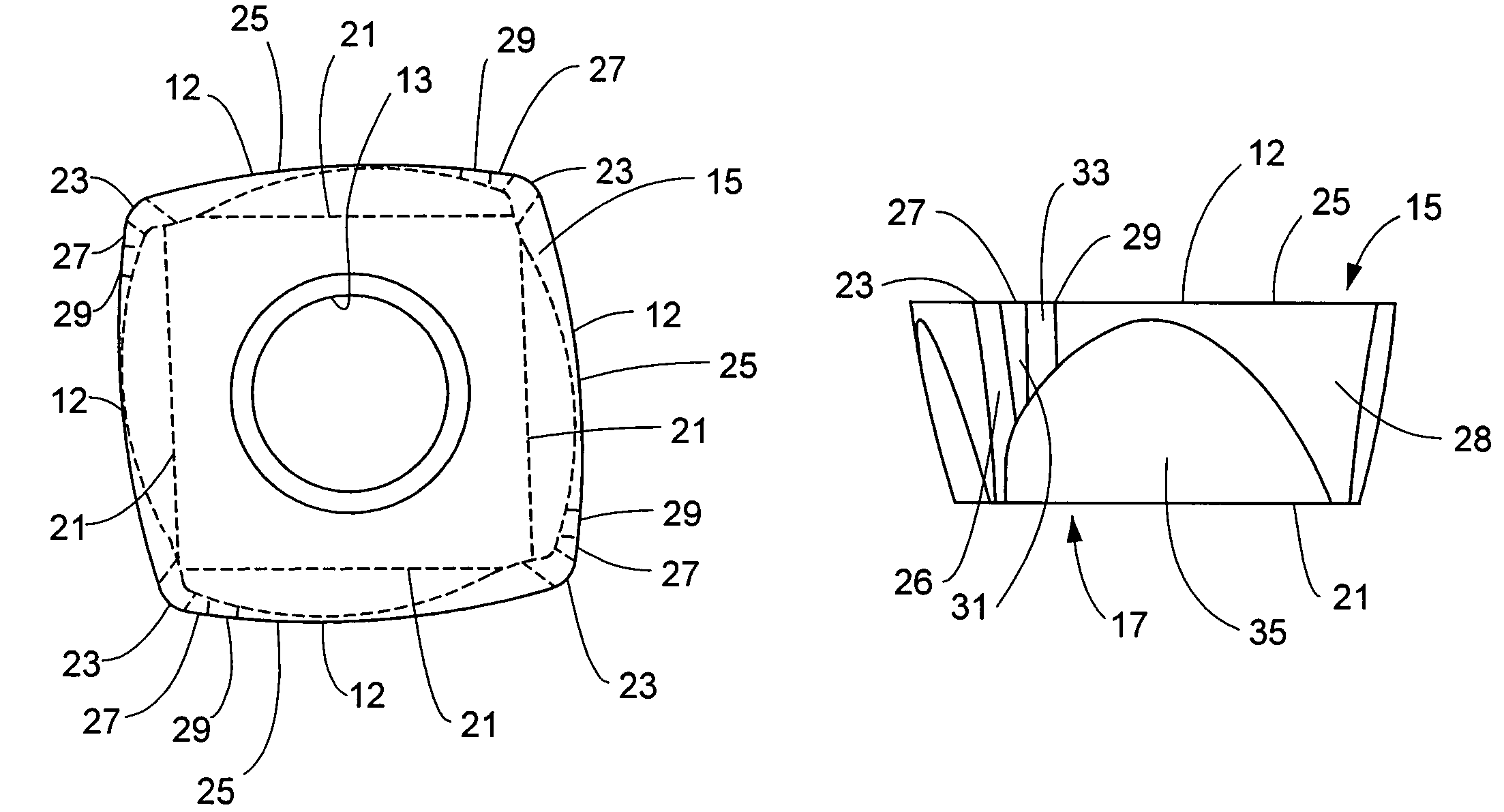
[0024]It is to be understood that certain descriptions of the present invention herein have been simplified to illustrate only those elements and limitations that are relevant to a clear understanding of the present invention, while eliminating, for purposes of clarity, other elements. Those of ordinary skill in the art, upon considering the present description of the invention, will recognize that other elements and / or limitations may be desirable in order to implement the present invention. However, because such other elements and / or limitations may be readily ascertained by one of ordinary skill upon considering the present description of the invention, and are not necessary for a complete understanding of the present invention, a discussion of such elements and limitations is not provided herein. For example, as discussed herein, embodiments of the cutting inserts of the present disclosure may be produced in the form of face milling inserts and other inserts for materials cuttin...


PUM

PropertyMeasurementUnit
diameteraaaaaaaaaa
diameteraaaaaaaaaa
diameteraaaaaaaaaa

Abstract

A cutting insert for milling operations, such as, face milling, slot milling, plunge milling, and ramping operations. The cutting insert exhibits a combination of favorable cutting edge strength, and unique cutting edge geometry, thus, allowing milling operations at relatively high feed rates. The cutting insert includes at least four cutting edges, wherein at least one of the cutting edges is a convex cutting edge. Certain embodiments of square cutting inserts will have four convex cutting edges which may be connected by nose corners. The convex cutting edge may comprise at least one of a circular arc, a portion of an ellipse, a portion of a parabola, a multi-segment spline curve, a straight line, or combinations of these. Wherein the convex cutting edge comprises a circular arc, the circular arc may have a radius greater than or equal to two times a radius of the largest circle that may be inscribed on the top surface.

Description

FIELD OF THE INVENTION[0001]The present disclosure is directed to a cutting insert. The cutting insert exhibits a combination of favorable cutting edge strength, and unique cutting edge geometry, thus, allowing milling operations at relatively high feed rates and may be useful in face milling, slot milling, plunge milling, and ramping operations.DESCRIPTION OF THE INVENTION BACKGROUND[0002]Traditional machining methods, which are the principal means of removing metal from workpieces, include chip cutting (such as milling, drilling, turning, broaching, reaming, and tapping) and abrasive machining methods (such as sanding, grinding, and polishing. One such chip cutting process, face milling, may be useful to produce a generally flat surface on a workpiece. A face milling tool or “face mill” is so named because the flat workpiece surface is produced by action of the face of the tool, although the outside diameter or bevel cutting edge removes most of the stock. In a typical application...

Claims


Application Information

Patent Timeline
Patent Type & Authority Patents(United States)
IPC IPC(8): B23B27/16B23C5/20
CPCB23C5/202B23C5/06B23C5/205B23C5/207B23C2200/125B23C2200/203Y10T407/23Y10T407/235Y10T409/303752Y10T407/1924Y10T407/191Y10T407/2274B23C2220/44B23C5/20B23C5/16
Inventor FESTEAU, GILLESDUFOUR, JEAN-LUCFANG, X. DANIELWILLS, DAVID J.
Owner KENNAMETAL INC
Why Eureka
Try Eureka