
Insert film used for forming resin panel, process for producing the film and resin panel using the film

Inactive Publication Date: 2007-05-22
TOYOTA IND CORP
View PDF9 Cites 17 Cited by
  • Summary
  • Abstract
  • Description
  • Claims
  • Application Information

AI Technical Summary

Benefits of technology

[0015]A first object of the present invention is to provide a resin panel that can prevent an ink flow on a printed part when producing the resin panel or a generation of a gap between a printed part and a film or sheet with the passage of time after use, by a simple structure and at the same time without using a specific printing ink.

Problems solved by technology

However, glass has high specific gravity.
However, the ink has poor adhesiveness with a polycarbonate, which is a material of the resin film 34.
Further, there are the same problems, not limited to just the resin window, in the case where the desired pattern is formed on the surface of a resin panel by integrally molding an insert film or sheet having a printed part on the surface of a molten injection molded resin.
However, in the case that the ink flow is prevented by controlling pressure and speed of the resin to be injected, as disclosed in Japanese Patent Application Laid-Open No. 6-270188, it is necessary to set proper conditions according to a shape and a size of a resin panel, and also there is the problem that a gate shape or a cavity depth of a mold is restrictive.
However, even if the surface of a pattern (printed part) is covered with a saturated thermoplastic polyester resin, adhesiveness between the ink and the insert film is poor.
As a result, when receiving a large shear force in injecting a molding material, it is difficult to prevent ink flow due to lifting of a part of the printed part.
Further, if a saturated thermoplastic polyester resin is contained in an ink, it results in diluting the ink.
As a result, light transmission rate is not sufficiently suppressed by such a thickness obtained by a general printing method.
On the other hand, if an amount of carbon or pigment in an ink is increased to thicken the ink, there is the problem that inconveniences tend to occur in printing.

Method used


Image

  • Insert film used for forming resin panel, process for producing the film and resin panel using the film
  • Insert film used for forming resin panel, process for producing the film and resin panel using the film
  • Insert film used for forming resin panel, process for producing the film and resin panel using the film

Examples


Embodiment Construction

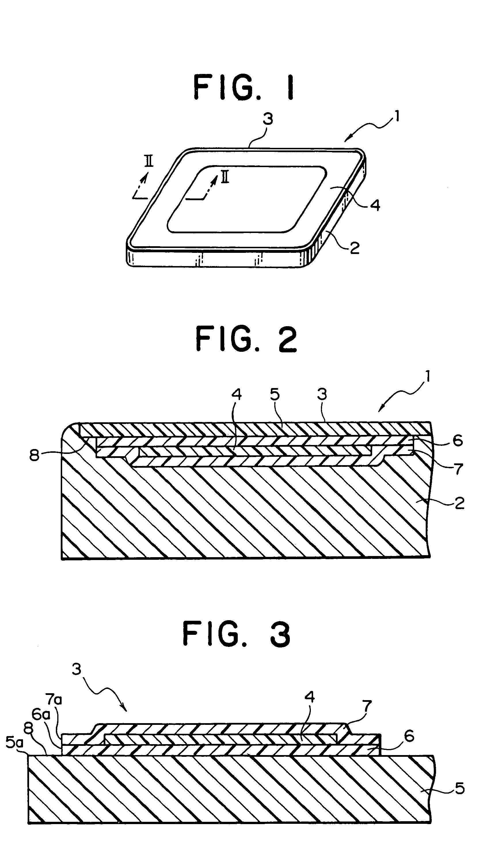
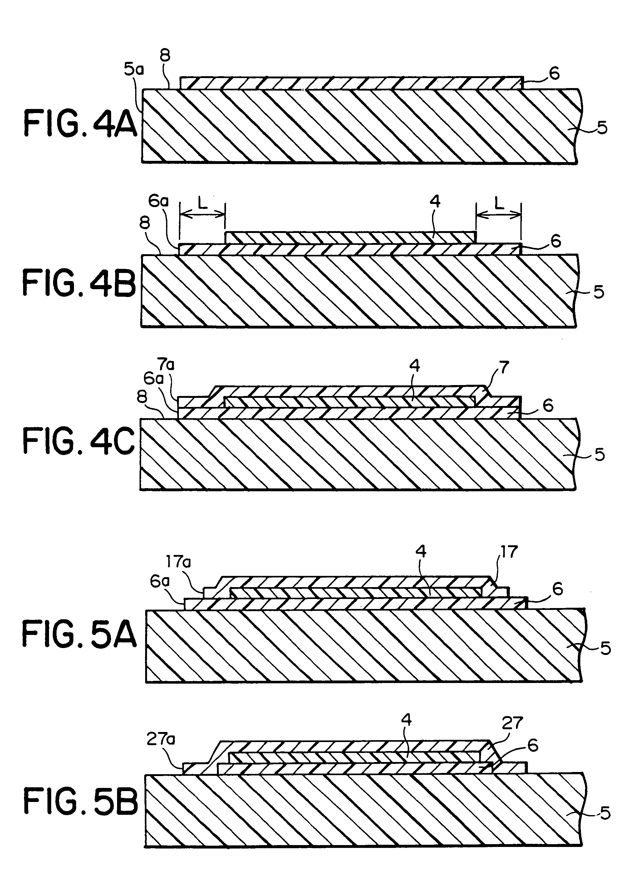
[0028]One practical embodiment in which the present invention is embodied in a resin window of automobiles is hereinafter explained according to FIGS. 1 to 4.

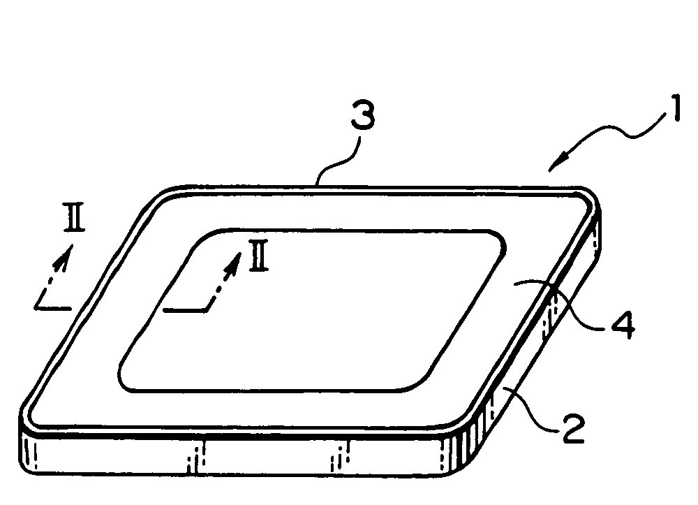
[0029]As shown in FIGS. 1 and 2, a resin window 1 as a resin panel comprises a resin-made panel body 2 and an insert film 3 having the inside thereof a printed part 4 as a trimming part (blackout) formed along a periphery of the insert film 3, the insert film being integrally molded with the surface of the panel body by insert molding. The material of the panel body 2 is polycarbonate. In FIG. 1, the printed part 4 is actually the state that the entire surface thereof is completely coated with an ink of a dark color such as black.

[0030]As shown in FIG. 3, the insert film 3 comprises a resin film or sheet 5 (hereinafter referred to as “resin film 5” for simplicity), a first binder layer 6 applied to one side of the resin film 5, the printed part 4 formed on the first binder layer 6, and a second binder layer 7 formed so as to co...


PUM

PropertyMeasurementUnit
Areaaaaaaaaaaa

Abstract

An insert film having a printed part is integrally molded to a surface of a panel body made of a resin by an insert molding. The printed part is printed on a first binder layer applied to a resin film and also is formed on the resin film in a state such of being sealed with the first binder layer and a second binder layer applied on the printed part. The printed part is formed as a trimming portion (blackout) along a peripheral portion of the resin film, and an area is formed between the peripheries of the first binder layer and the second binder layer and the periphery of the resin film.

Description

BACKGROUND OF THE INVENTION[0001]1. Field of the Invention[0002]The present invention relates to an insert film used for forming a resin panel, a process for producing the insert film and a resin panel using the insert film. More particularly, it relates to an insert film having provided therein a printed part.[0003]2. Description of the Related Art[0004]Conventionally, glass is used as a material for a window member of automobiles. However, glass has high specific gravity. Therefore, to attempt making the window material lightweight, a resin window using a resin such as polycarbonates or acrylic resins as a material thereof in place of glass is also used. For example, Japanese Patent Application Laid-Open No. 6-170883 discloses that, because a resin window has a softer surface as compared with a glass window, insert molding is conducted for integral molding by injecting a molten resin in a mold in a state such that a resin (polycarbonate) film or sheet in which one side has been su...

Claims


Application Information

Patent Timeline
IPC IPC(8): B44C5/08B29C45/14B32B27/08
CPCB29C45/14811B32B27/08B29K2715/006B29L2031/3052Y10T428/23Y10T428/24802Y10T428/24661Y10T428/269Y10T428/24868Y10T428/236Y10T428/31507B32B27/365B32B2605/006B32B2369/00
Inventor OAMI, KOTAROSUZUMURA, MASAAKI
Owner TOYOTA IND CORP
Learn More