Systems and methods for inspecting coatings, surfaces and interfaces

a technology of surface coating and inspection method, applied in the direction of material flaw investigation, optical radiation measurement, instruments, etc., can solve the problems of not being able the technique of properly prepared surface may diminish the perceived quality of exterior paint, and the inability to efficiently and effectively detect subsurface anomalies, etc., to achieve the effect of minimizing the need for operator involvement and efficient detection of subsurface anomalies

Inactive Publication Date: 2007-05-22
TOYOTA MOTOR CO LTD +1
View PDF36 Cites 64 Cited by
  • Summary
  • Abstract
  • Description
  • Claims
  • Application Information

AI Technical Summary

Benefits of technology

[0008]Accordingly, the present invention is intended to address and obviate problems and shortcomings and otherwise improve previous systems and methods for inspecting coatings on surfaces, and particularly for automotive paints and coatings, bonded joints and other surfaces. According to some aspects, techniques are provided for more efficiently detecting subsurface anomalies. In accordance with other aspects, techniques are provided for realtime applications, and for minimizing need for operator involvement.

Problems solved by technology

Defects occurring in the coating method of a properly prepared surface that may diminish the perceived quality of the exterior paint include, but are not limited to, dust, hair, metallic particles, over spray, incomplete spray, stripping and flake penetration.
Previously, evaluation of the quality of the paint finish was often based on human inspection, which can be a tedious and subjective method and one that requires meaningful skill and training.
However, this technique is not particularly effective for complex, curved and / or hidden geometries (i.e. automobile bodies) because of its sensitivity and dependence on reflection and scattering angles.
However, such inspection techniques are based solely on the spatial analysis of pixel values with that of known (standard) values without any account for the temporal behavior of the pixel values (e.g., change of temperature over time).
In addition, while other techniques have been utilized to measure the change of temperature over time, such techniques do not compare measured change of temperature of pixels of the same data file to that of surrounding pixels, and therefore fail to efficiently and effectively detect subsurface anomalies.
Such procedures can also require operator intervention, significant time requirements, and / or computational complexities not suited for realtime applications.

Method used


Image

  • Systems and methods for inspecting coatings, surfaces and interfaces
  • Systems and methods for inspecting coatings, surfaces and interfaces
  • Systems and methods for inspecting coatings, surfaces and interfaces

Examples


example 1

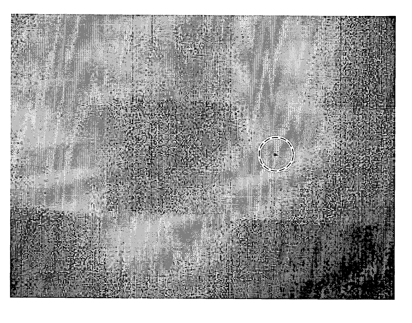
[0103]In this example, an infrared system is installed on a production line for the detection of a chipped spot in an anti-corrosive coating. FIG. 8 shows a thermal profile of a steel structure coated with an anti-corrosive protective coat with a chipped spot representing a different thermal signature from its surroundings. (The same infrared detection system can be used for missed coat spots (thin paint) detection.) Those chipped spots expose the steel substrate which has a different thermal inertia from that of the coat making it an easy target to detect. This application is shown in FIG. 9 which shows a visual image of a thin paint area and the corresponding thermal profile. In accordance with principles of the present invention, the change in temperature over time of the area can be determined by monitoring the thermal profile over time, and defects can thereby be determined based upon the change in temperature versus the expected change, such as according to the methods describ...

example 2

[0104]In this example, an infrared system is used to investigate the adhesion layer integrity of a polymer plastic welded joint, according to additional principles of the present invention. The joints in this example are made from a composite of two layers of a polymer (High Density Polyethylene HDPE) with an adhesive interface. Carbon pigments have been added to one of HDPE layers for darkening to provide better thermal absorption and emission properties for insulation purposes. The geometry of the joints under inspection in this example, along with a cross section, are shown in FIG. 10, and the geometry of this example is represented as two cups welded together at the neck region. The bond interface is located between the HDPE layer and the rest of the geometry. In this example, the infrared thermography can be applied in two modes; a transmission mode where the stimulant (e.g., source) and the detector are located on opposite sides. For the reflection mode, the stimulant and dete...

example 3

[0111]In this example, and in accordance with additional aspects of the invention, infrared “self-referencing” thermography is again applied. As mentioned, this technique eliminates the need for prior knowledge of a defect free area to allow automatic identification of defects from thermal profiles. The basis of this technique is to divide the thermogram profile into small, localized neighborhoods using the assumption that these neighborhoods exhibit the non-defective behavior for the thermal contrast computation. This technique can be utilized in both static (hot spot detection) and dynamic (Infrared Tomography) cases.

[0112]The thermal contrast computation is used in processing the data in this example, because of its ability to enhance the image quality and consequently the defect visibility. Thus, contrast could be computed by monitoring changes in temperatures in multiple profiles taken successively. Many definitions could be used to compute the thermal contrast. Such definition...


PUM

PropertyMeasurementUnit
temperatureaaaaaaaaaa
temperaturesaaaaaaaaaa

Abstract

A system for detecting defects in paint coatings includes a temperature manipulation apparatus configured to change the temperature of a surface and a coating applied to the surface. The system may further include an infrared sensor for measuring the change in temperature (over time) of the surface and coating and a processor to compare the measured change in temperature of the surface and coating to an expected change of temperature (over time) in order to determine anomalies in the coatings. A self-referencing method of determining defects is also disclosed, wherein surrounding pixels are utilized as a reference in the detection process for calculating the change in temperature of each pixel. In addition, application of the inventive aspects to inspection of adhesion interfaces is also disclosed.

Description

CROSS REFERENCE TO RELATED APPLICATION[0001]This application is a continuation-in-part of prior copending U.S. application Ser. No. 10 / 629,426 filed Jul. 29, 2003, the entire disclosure of which is hereby incorporated by reference herein.FIELD OF THE INVENTION[0002]This invention relates to systems and methods for detecting defects in surfaces and to coatings applied to substrates. More particularly, this invention relates to systems and methods for detecting surface and subsurface defects in vehicle paint coatings, surfaces, and interfaces using an infrared camera.BACKGROUND OF THE INVENTION[0003]One of the most important methods in high quality automobile and other vehicle or machine production involves the inspection of the exterior appearance (i.e. the quality of the paint finish on a part). Usually, an automobile shell, for example, receives at least four coatings including a protective coat, an adhesion aid coat, a paint coat and a clear coat. Defects occurring in the coating ...

Claims


Application Information

Patent Timeline
Patent Type & Authority Patents(United States)
IPC IPC(8): G01N21/88B05D1/00G01N25/72
CPCG01N25/72B05B15/1207B05D3/0263B05D5/005B05B16/20
Inventor SAITO, KOZOHASSAN ALI, MOHAMMED I.NUMASATO, AKIRAOMAR, MOHAMMED A.SAKAKIBARA, MASAHITOSUZUKI, TOSHIKAZUTANIGAWA, YASUO
Owner TOYOTA MOTOR CO LTD
Why Eureka
Try Eureka