Communication systems for use with magnetic resonance imaging systems

a technology of communication system and magnetic resonance imaging, applied in the field of systems and methods of communication, can solve the problems of substantial site dedication, less than optimal alternative, and not very portabl

Inactive Publication Date: 2007-05-22
BAYER HEALTHCARE LLC
View PDF57 Cites 54 Cited by
  • Summary
  • Abstract
  • Description
  • Claims
  • Application Information

AI Technical Summary

Benefits of technology

[0013]Another objective of the invention is to provide a system and method of communicating reliably between the equipment located in the control and scanner rooms in which the equipment in either or both of the rooms can be moved without adversely affecting the quality of the communications or the images obtained during MRI scanning procedures.
[0025]The invention also provides a method of communicating across an isolation barrier separating the scanner and control rooms of an MRI suite. The method comprises the steps of: (a) positioning first and second transceivers within the scanner and control rooms, respectively; (b) interconnecting a first antenna and a second antenna; and (c) positioning the first and second antennas within the MRI suite. The first antenna is positioned within the scanner room approximate an interior side of the barrier, and is capable of receiving from and transmitting to the first transceiver. The second antenna is positioned within the control room approximate an exterior side of the barrier, and is capable of receiving from and transmitting to the second transceiver. The method also includes the step of configuring the first and second transceivers to use a desired range of radio frequencies outside the range of operation of the MRI suite in communicating across the isolation barrier via the first and second antennas, and thus avoiding adverse affects upon the operation of the scanner in the MRI suite. In a related aspect, the method may also include the step of connecting a filter between the first and second antennas, preferably on the exterior side of the barrier, to prevent radio frequencies outside of the desired range from being transmitted across the isolation barrier.

Problems solved by technology

The remote location of the controller creates various problems associated with the installation and operation of these injector systems.
One such problem is the need to provide a communication link between the externally located controller and the injector control unit within the shielded scanner room, without introducing extraneous electromagnetic radiation.
These alternatives have proven to be less than optimum because spurious electromagnetic radiation can arise, or be coupled into the scanner room from external sources, from the presence of the various supply cables within the shielded room of the MRI suite.
Additionally, the MRI systems that employ these alternatives often require substantial site dedication and are, therefore, not very portable.
One such shortcoming is that the use of cables to connect to the transceivers on either side of the window inevitably restricts the mobility of both the controller and the injection control unit in the control and scanner rooms, respectively.

Method used


Image

  • Communication systems for use with magnetic resonance imaging systems
  • Communication systems for use with magnetic resonance imaging systems
  • Communication systems for use with magnetic resonance imaging systems

Examples


first embodiment

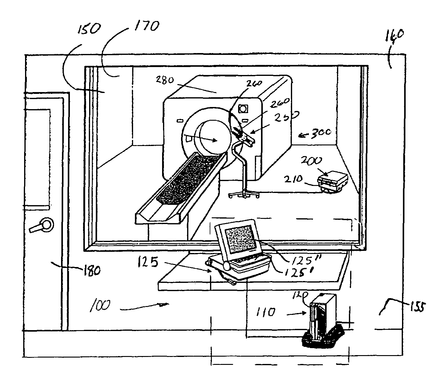
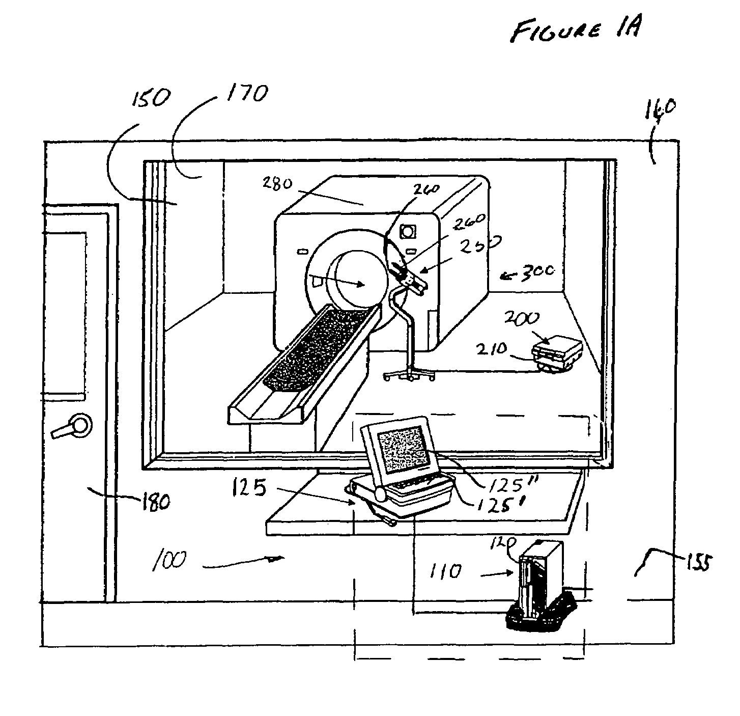
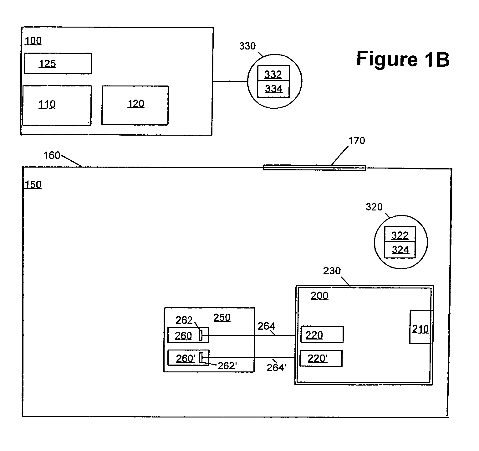
[0045]FIG. 1B illustrates the present invention. For control of injection head unit 250 by system controller 100, communication must be maintained between the system controller 100 and the injection control unit 200. In this embodiment, the injector control unit 200 of the injection system is preferably in communication with a communication unit 320 that preferably includes a transmitter 322 and a receiver 324. Likewise, the controller 100 of the injection system is preferably in communication with a communication unit 330. Communication unit 330 preferably includes a transmitter 332 and a receiver 334. Transmitters and receivers for use in the present invention can also be combined in transceivers as is known in the art.

[0046]In one aspect of the present invention, transmitter 322 and receiver 324 of communication unit 320 are in wireless or cableless communication with those in communication unit 330. For example, there is preferably no communication line (e.g., fiber optic cablin...

second embodiment

[0050]FIG. 1D illustrates the present invention. In the embodiment illustrated in FIG. 1B, RF communication unit 330 (including, for example, transmitter 332 and receiver 334) is positioned outside of scanner room 150. In the embodiment of FIG. 1D, however, RF communication unit 330 is positioned within scanner room 150. Moreover, RF communication unit 330 is connected via a non-RF-interfering cabling 340 (for example, fiber optic cabling) through tuned port 350 to the controller 100 of the injection system, which is located in control room 155. As used herein and commonly in the MR arts, the term “tuned port” refers to an opening or aperture in shield 160 that is designed / dimensioned to prevent transmission of energy of certain frequencies therethrough. Communication unit 330 communicates with RF communication unit 320 as described above.

[0051]The RF energy used in the communications system of the present invention is preferably in the range of approximately 2.4 to 2.48 GHz, which ...

third embodiment

[0056]FIG. 2 illustrates the present invention. In this embodiment, the injector control unit 200a of the injection system includes a communication unit 320a. Communication unit 320a preferably includes a transmitter 322a and a receiver 324a. Likewise, the controller 100a of the injection system includes a communication unit 330a. Communication unit 330a features a transmitter 332a and a receiver 334a. As described above, the transmitter / receiver pairings can be in the form of transceivers.

[0057]In this embodiment, optical and / or infrared light is used to transmit information between controller 100a and injector control unit 200a through, for example, window 170. Such communication can be interrupted, however, if there is not a direct “line of sight” between the communication unit 330a of controller 100a and the communication unit 320a of injection control unit 200a. To assist in providing a substantially direct line of sight, an optical / infrared transceiver 126a in communication wi...


PUM


Abstract

An antenna coupling enables communication across a barrier to radio frequencies. The antenna coupling comprises first and second antennas. The first antenna is adapted for positioning on a first side of the barrier, and is capable of receiving from and transmitting to a first transceiver disposed on the first side. The second antenna is adapted for positioning on a second side of the barrier, and is capable of receiving from and transmitting to a second transceiver on the second side. The interconnection of the first and second antennas through the barrier comprises the antenna coupling. The antenna coupling enables the first and second transceivers to communicate across the barrier over the desired range(s) of radio frequencies. In a related aspect, the antenna coupling may also include a filter interconnected between the first and second antennas to prevent radio frequencies outside of the desired range(s) from being transmitted across the barrier.

Description

CROSS REFERENCE TO RELATED APPLICATIONS[0001]This application for patent is a continuation-in-part, and claims the benefit, of U.S. application Ser. No. 09 / 586,140, filed Jun. 2, 2000 now U.S. Pat. No. 6,704,592. The prior application has been assigned to the assignee of the invention(s) described and claimed below, and its teachings are incorporated into this document by reference.FIELD OF THE INVENTION[0002]The invention relates generally to systems and methods of communication, and, especially to systems and methods of communication for use in magnetic resonance imaging (MRI) and spectroscopy procedures. More particularly, the invention pertains to a system and method of wirelessly communicating between equipment located in, and which is movable within, the control and scanner rooms of an MRI suite.BRIEF DESCRIPTION OF RELATED ART[0003]The following information describes one of the many possible environments in which the invention can be used. It is provided to assist the reader ...

Claims


Application Information

Patent Timeline
Patent Type & Authority Patents(United States)
IPC IPC(8): G01V3/00A61B5/00A61B5/055G01R33/28
CPCG01R33/283A61B5/055A61B5/0017A61B5/002
Inventor GRIFFITHS, DAVID M.MISIC, GEORGE J.MONSKI, WILLIAM J.NG, MO SHUENBROSOVICH, JOHN A.
Owner BAYER HEALTHCARE LLC
Why Eureka
Try Eureka