High throughput AES architecture

Active Publication Date: 2007-05-22
MICROCHIP TECH INC
View PDF11 Cites 61 Cited by
  • Summary
  • Abstract
  • Description
  • Claims
  • Application Information

AI Technical Summary

Benefits of technology

[0008]The present invention is a low latency, non-pipelined AES architecture. Hardware is provided for one encryption round, which is r

Problems solved by technology

Unfortunately, this arrangement is incompatible with pipelin

Method used


Image

  • High throughput AES architecture
  • High throughput AES architecture
  • High throughput AES architecture

Examples


Example

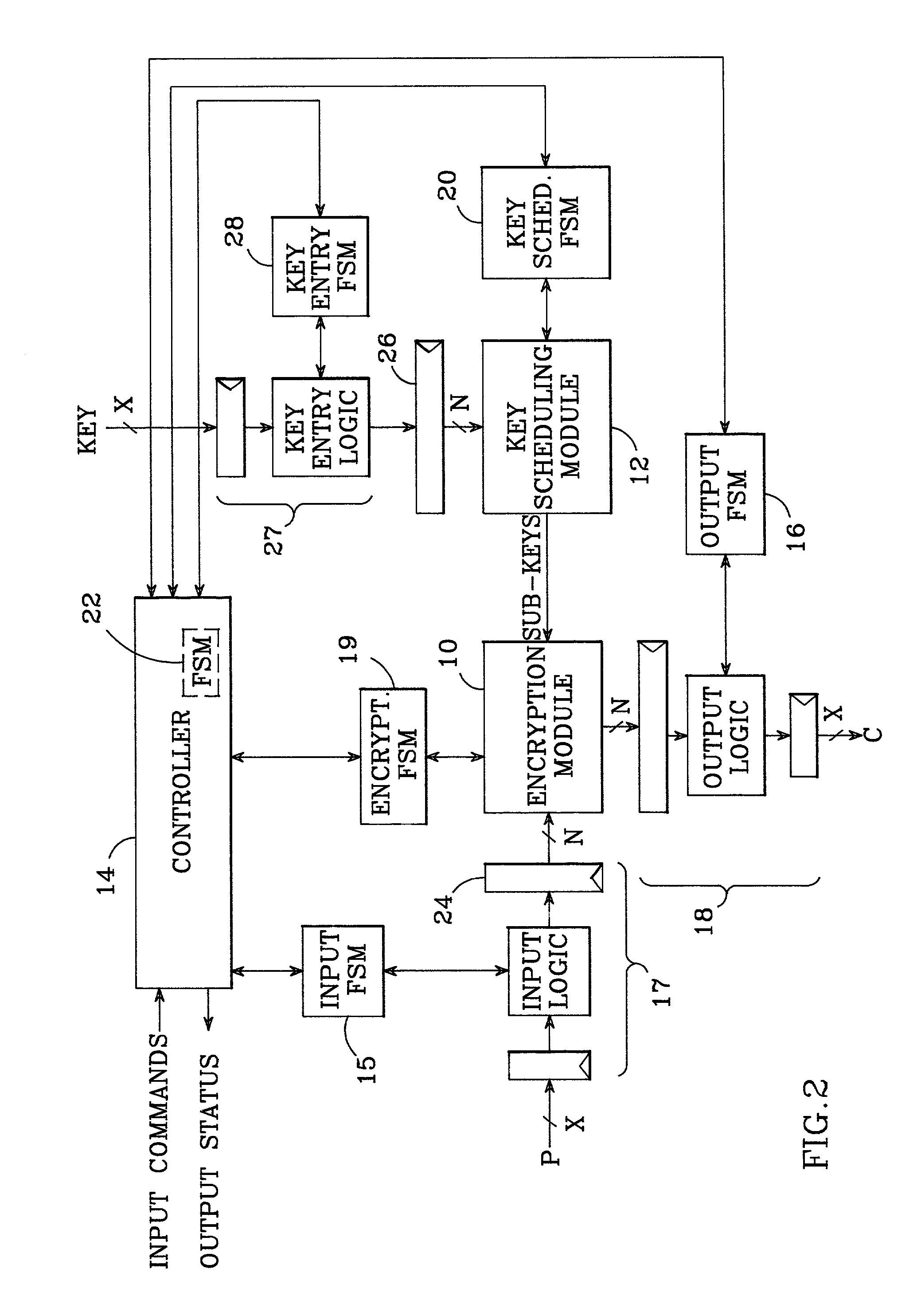
[0019]An AES architecture in accordance with the present invention is shown in FIG. 2. When properly arranged, the present architecture provides high throughput, even with feedback modes of operation. At the heart of the architecture are an encryption module 10, a key scheduling module 12, and a controller 14. Encryption module 10 is made maximum parallel; i.e., all operations that can occur in parallel, do occur in parallel. This means that every bit of an N-bit data block is processed simultaneously through the encryption module. Thus, if the data block length N is chosen to be 256 bits, the encryption module receives and processes all 256 bits at once. Furthermore, the encryption module implements one round of the AES algorithm in one clock cycle.

[0020]The key scheduling module 12 is also made maximum parallel, such that the sub-keys required by encryption module 10 are generated in one clock cycle, in parallel with the encryption module.

[0021]Encryption module 10 and key schedul...


PUM


Abstract

An advanced encryption system (AES) architecture includes a maximum parallel encryption module which implements one round of the AES algorithm in one clock cycle, and a maximum parallel key scheduling module which generates sub-keys in one clock cycle in parallel with the encryption module, thereby permitting feedback modes of operation to be used without adversely affecting AES throughput. A controller controls the operation of the encryption and key scheduling modules such that one round is completed per clock cycle. The controller is preferably part of a hierarchical distributed control scheme comprising communicating finite state machines (FSMs). The architecture also preferably includes asynchronous input and output buffers.

Description

BACKGROUND OF THE INVENTION[0001]1. Field of the Invention[0002]This invention relates to the field of encryption systems, and particularly to advanced encryption standard (AES) architectures.[0003]2. Description of the Related Art[0004]The advanced encryption standard (AES) is a new encryption standard which implements the Rijndael algorithm. The Rijndael algorithm accepts data blocks and key sizes of 128, 192, or 256 bits; the AES implementation is a symmetric block cipher with 128 bit data blocks and a key size that can be chosen from 128, 192, or 256 bits.[0005]Several possible implementation modes of the AES standard are shown in FIG. 1. The AES algorithm may be employed as an electronic code book (ECB) which receives plaintext (P) and produces an encrypted output (C). The algorithm may also be employed in one of several feedback modes of operation; such feedback modes include Cipher Block Chaining (CBC), Cipher Feedback (CFB), and Output Feedback (OFB).[0006]Ideally, an implem...

Claims


Application Information

Patent Timeline
IPC IPC(8): H04L9/00H04L9/28H04L9/06
CPCH04L9/0631H04L2209/125H04L2209/24
Inventor VERBAUWHEDE, INGRID
Owner MICROCHIP TECH INC
Why Eureka
Try Eureka