Hydrostatic continuously variable transmission

a transmission and continuously variable technology, applied in the direction of fluid couplings, gearings, couplings, etc., can solve the problem of piping that requires a lot of labor, and achieve the effect of simple cooling structur

Active Publication Date: 2007-05-29
KUBOTA CORP
View PDF5 Cites 17 Cited by
  • Summary
  • Abstract
  • Description
  • Claims
  • Application Information

AI Technical Summary

Benefits of technology

[0004]In view of this, an object of the present invention is to provide a simple cooling structure of a hydrostatic continuously variable transmission.

Problems solved by technology

A number of parts for connecting the pipes are required, and piping requires much labor.

Method used


Image

  • Hydrostatic continuously variable transmission
  • Hydrostatic continuously variable transmission
  • Hydrostatic continuously variable transmission

Examples


Embodiment Construction

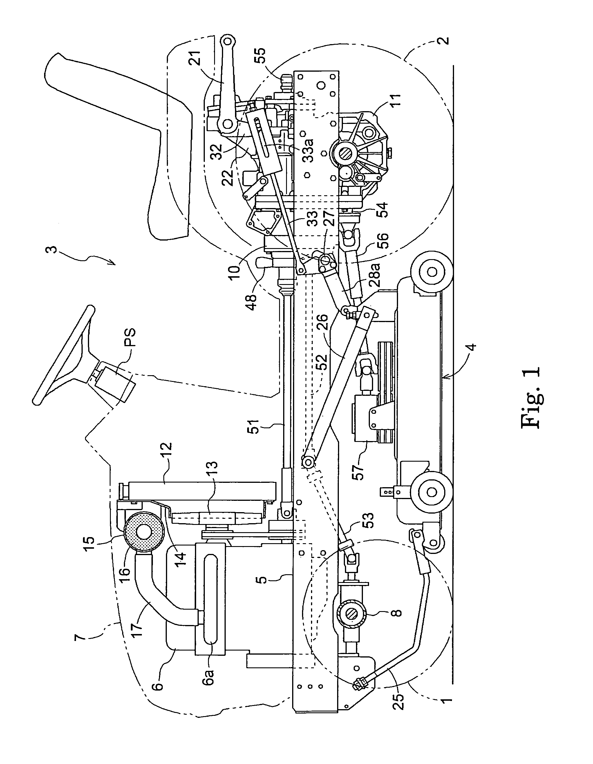
[0018]FIG. 1 illustrates a general-purpose tractor which is an exemplary work vehicle in which a hydrostatic continuously variable transmission is used as an automotive transmission. The tractor is configured as a lawnmower, in which a mower 4 is linked to a lower portion of a four-wheel drive vehicle 3 comprising a small-diameter front wheel 1 which is controlled by a power steering operation, and a large-diameter rear wheel 2 (main drive wheel), in a manner which allows the mower 4 to freely move upward and downward.

[0019]The vehicle 3 includes a pair of left and right main frames 5 made of thick board material which are extending from the front to the rear. An engine 6 (power source) is provided at a front portion of the main frame 5 with a rotation axis center thereof being directed back and forth, and is covered with a bonnet 7. A front axle case 8 which supports the front wheel 1 is linked to a lower front portion of the main frame 5 in a manner which allows the front axle cas...


PUM


Abstract

A hydrostatic continuously variable transmission comprises: a hydraulic pump; a power input shaft engaged with the hydraulic pump to transmit power from a power source to the hydraulic pump; a hydraulic motor in hydraulic communication with the hydraulic pump; a casing that houses the hydraulic pump and the hydraulic motor; a port block mounted to the casing, the port block having a block main body and a cover member connected to a power input side of the block main body, said cover member having an outer surface; a cooling hydraulic path provided in the port block in a region where the block main body and the cover member meet, the cooling hydraulic path being connected to a first hydraulic path in the port block, the cooling hydraulic path having a plurality of bends; a cooling fan provided on the power input shaft to provide air flow directly to the outer surface of the cover member.

Description

BACKGROUND OF THE INVENTION[0001]The present invention relates to a hydrostatic continuously variable transmission which is used as an automotive transmission in various work vehicles, such as a tractor, a lawnmower, a combine harvester, a rice transplanter, and the like.[0002]In hydrostatic continuously variable transmissions (HSTs), hydraulic fluid needs to be cooled since the hydraulic fluid is heated by friction. For example, as disclosed in JP No. 8-145168 A, charge fluid pumped from a charging pump is cooled through an oil cooler before being supplied into a charge fluid path.[0003]Conventionally, the oil cooler is provided in a cooling air path in a radiator of an engine, and the oil cooler is connected to related devices via external pipes. A number of parts for connecting the pipes are required, and piping requires much labor.SUMMARY OF THE INVENTION[0004]In view of this, an object of the present invention is to provide a simple cooling structure of a hydrostatic continuous...

Claims


Application Information

Patent Timeline
Patent Type & Authority Patents(United States)
IPC IPC(8): F16H61/40B60K11/00F16H39/14F16H57/02F16H57/04
CPCF16H39/02F16H57/0415F16H57/033
Inventor SHIBATA, TAKASHITOMIYAMA, YOSHIOKURAMOTO, TAKASHISHIMADA, HIROSHIKOMORIDA, TAKESHINISHIHARA, KENJIOSUGA, MASASHI
Owner KUBOTA CORP
Why Eureka
Try Eureka