Liquid measurements using capacitive monitoring

a capacitive monitoring and liquid measurement technology, applied in liquid transfer devices, instruments, machines/engines, etc., can solve problems such as lack of robustness of the device used to monitor and control aspiration and dispensing, and methods and techniques that do not measure the actual volume of liquid that is aspirated or dispensed, so as to improve the measurement of liquid and increase the reliability of the system

Inactive Publication Date: 2007-05-29
ORTHO-CLINICAL DIAGNOSTICS
View PDF38 Cites 11 Cited by
  • Summary
  • Abstract
  • Description
  • Claims
  • Application Information

AI Technical Summary

Benefits of technology

[0012]The present invention is directed to a method that solves the foregoing problems of improving the measurement of a liquid being aspirated or dispensed by a probe, particularly by directly measuring the amount of liquid in a tip or probe and increasing the reliability of the system, as well increasingly consolidating the components of the system nears the probe or probe tip where the measurement is being taken.

Problems solved by technology

These methods and techniques, however, do not measure the actual volume of liquid that is aspirated or dispensed.
Problems can arise if, for example, the probe is not fully immersed in the liquid or if there are air bubble(s) entrained in the liquid.
Other problems associated with much of the known art include lack of robustness of the device used to monitor and control aspiration and dispense.
That is, many of the known systems are susceptible to mechanical vibrations and other perturbations.
Yet other problems lie in the size of the systems to monitor aspiration and dispense in that known systems often require components away from the aspirating probe and probe tip.

Method used


Image

  • Liquid measurements using capacitive monitoring
  • Liquid measurements using capacitive monitoring
  • Liquid measurements using capacitive monitoring

Examples


Embodiment Construction

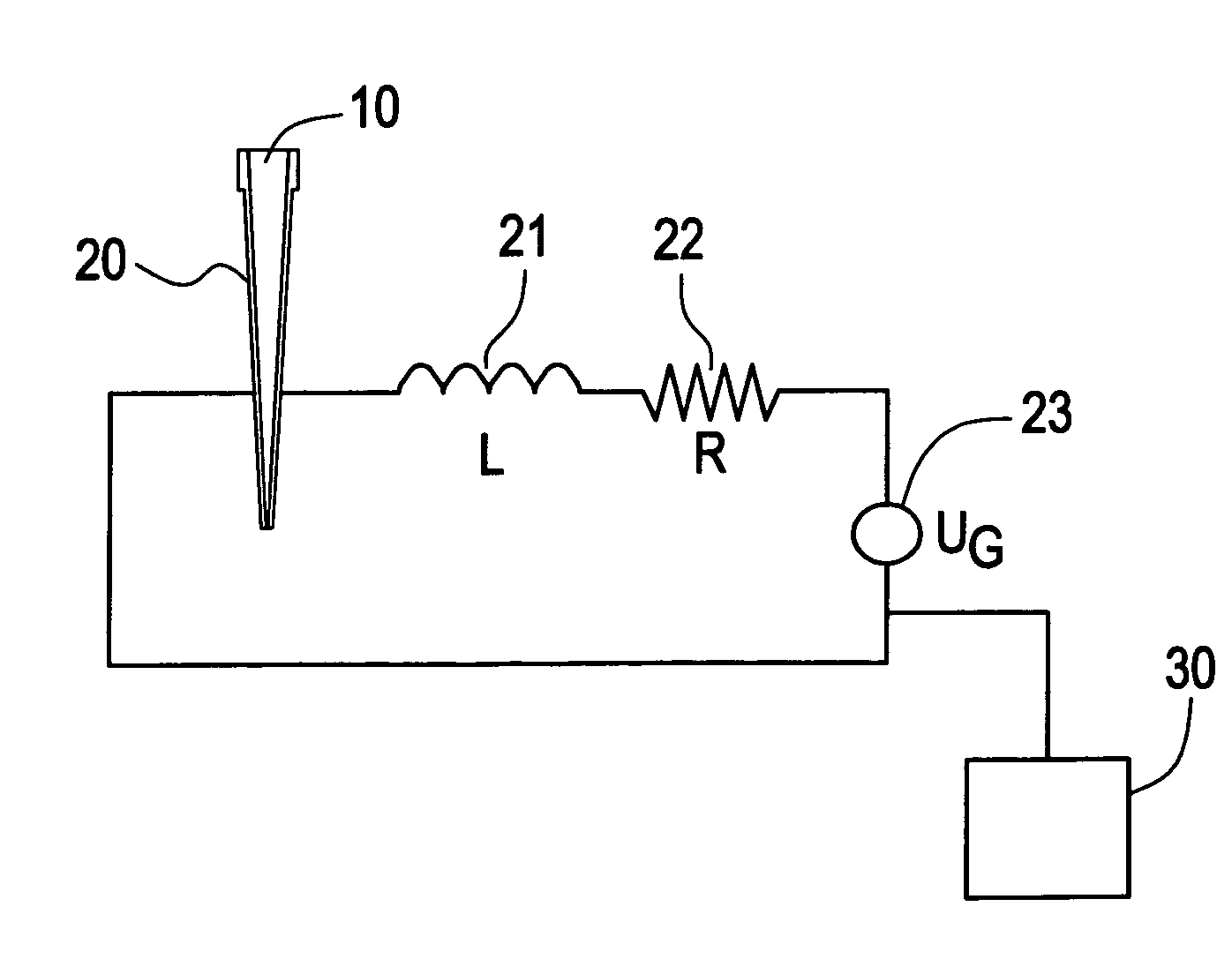
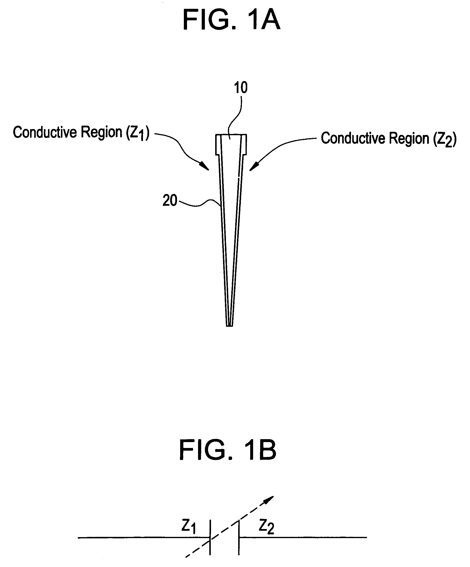
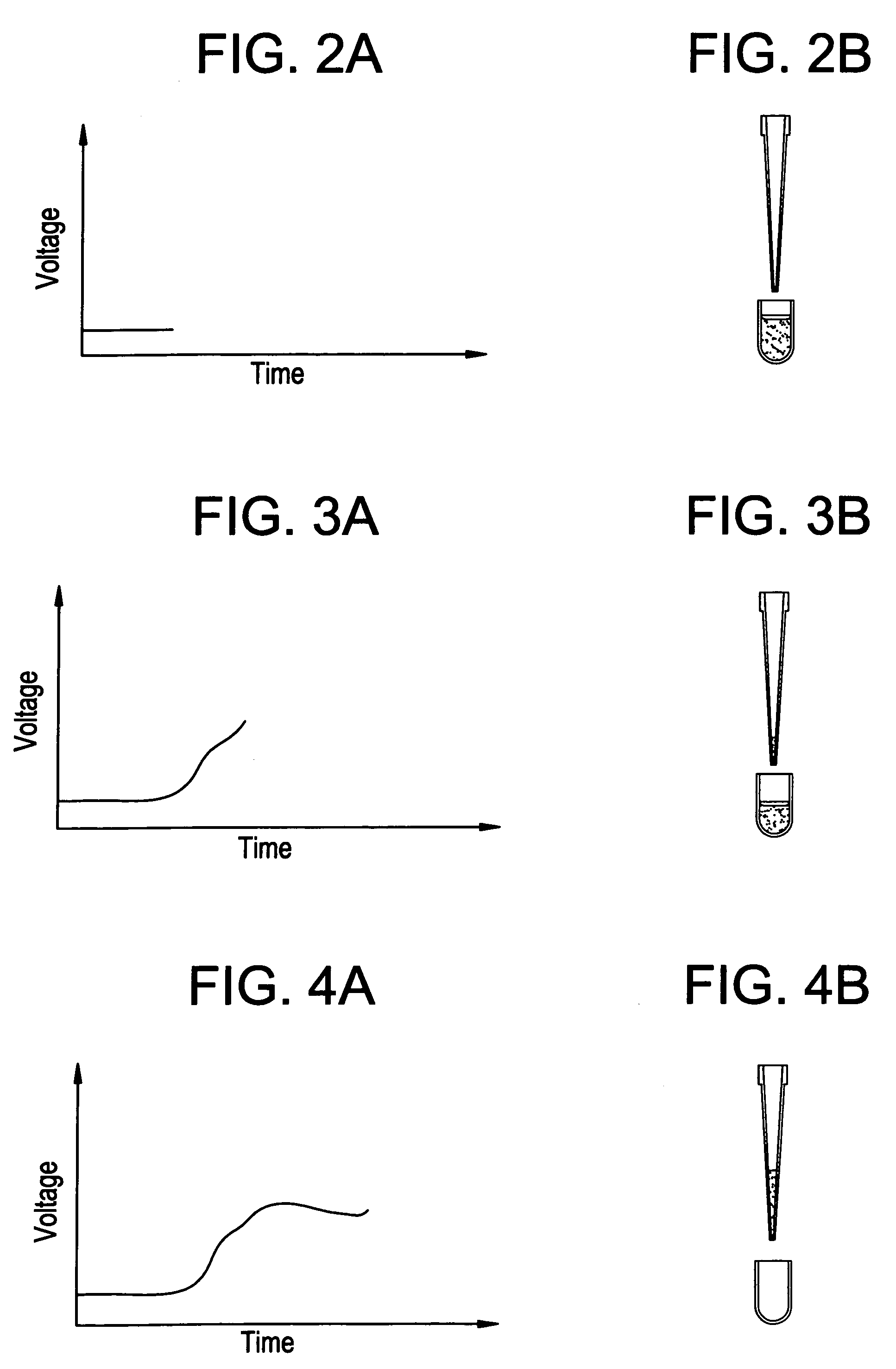
[0036]The present invention broadly relates to an apparatus and method for determining the volume of a liquid in the probe tip of a liquid aspiration and dispense probe. In the present invention, the probe tip is designed to act as a variable capacitor. When liquid is aspirated and / or dispensed, the varying volume alters the capacitance sensed in the disposable tip. The capacitance changes can be used to determine if liquid is present or not in the tip, and to determine the volume of liquid based on the dielectric properties of the liquid and the total capacitance value.

[0037]In other words, the present invention relies upon the relationship (described more fully below) between capacitance and the type and amount of material (i.e., liquid) between the electrodes of the capacitor. The amount will be related to the volume of liquid in the probe tip. The type of liquid (i.e., its dielectric constant) may or may not be known. If the dielectric constant is known, then determining volume ...


PUM

PropertyMeasurementUnit
capacitanceaaaaaaaaaa
frequenciesaaaaaaaaaa

Abstract

An apparatus for determining the volume of liquid in a probe tip of an aspirating or dispensing probe, such as those used in a diagnostic analyzer, includes: two electrodes on opposite sides of the probe tip and the electrodes and liquid form a variable capacitor; a resistor; a voltage source and the electrodes and resistor are in electrical communication in at least one of series, parallel or series and parallel to form an RC circuit; and a microprocessor in electrical communication with the RC circuit for converting an electrical signal to a volume of liquid in the probe tip. In a preferred embodiment, the probe tip is separate from the probe and is adapted to be fitted on the end of a probe for aspirating and dispensing a liquid. In another preferred embodiment, the apparatus further includes a solenoid, and the voltage source, electrodes, resistor, and solenoid are in electrical communication in at least one of series, parallel or series and parallel to form an RLC circuit, and the microprocessor is in electrical communication with the RLC circuit for converting an electrical signal to a volume of liquid in the probe tip. The apparatus can be used with a liquid have a known or unknown dielectric constant and can be used to determine the presence of bubbles in the liquid.

Description

BACKGROUND OF THE INVENTION[0001]1. Field of the Invention[0002]The present invention relates to measuring aspects of a liquid by determining the capacitance of a volume of liquid. More particularly, the present invention relates to using capacitance in a dispensing or aspirating probe, particularly in automated analyzers, such as chemistry or blood analyzers, to determine the volume of liquid in the probe tip or the presence of air bubbles in the liquid in the probe tip.[0003]2. Description of the Related Art[0004]Advances in industries utilizing chemical and biological processes have created a need for the ability to accurately and automatically dispense varying quantities of liquids for commercial, laboratory, and research uses, particularly in automated analyzers. Typically, an automated analyzer includes an automated liquid metering system that automatically aspirates a sample of liquid from a reservoir or test-tube containing patient sample and dispenses the liquid into anothe...

Claims


Application Information

Patent Timeline
Patent Type & Authority Patents(United States)
IPC IPC(8): G01F23/26A01G27/00B67D7/08G01F22/00G01N35/10
CPCG01F23/266G01F23/268G01N35/1016
Inventor BAKER, LEMONTLELIC, MUHIDIN
Owner ORTHO-CLINICAL DIAGNOSTICS
Why Eureka
Try Eureka