
Payload adapter

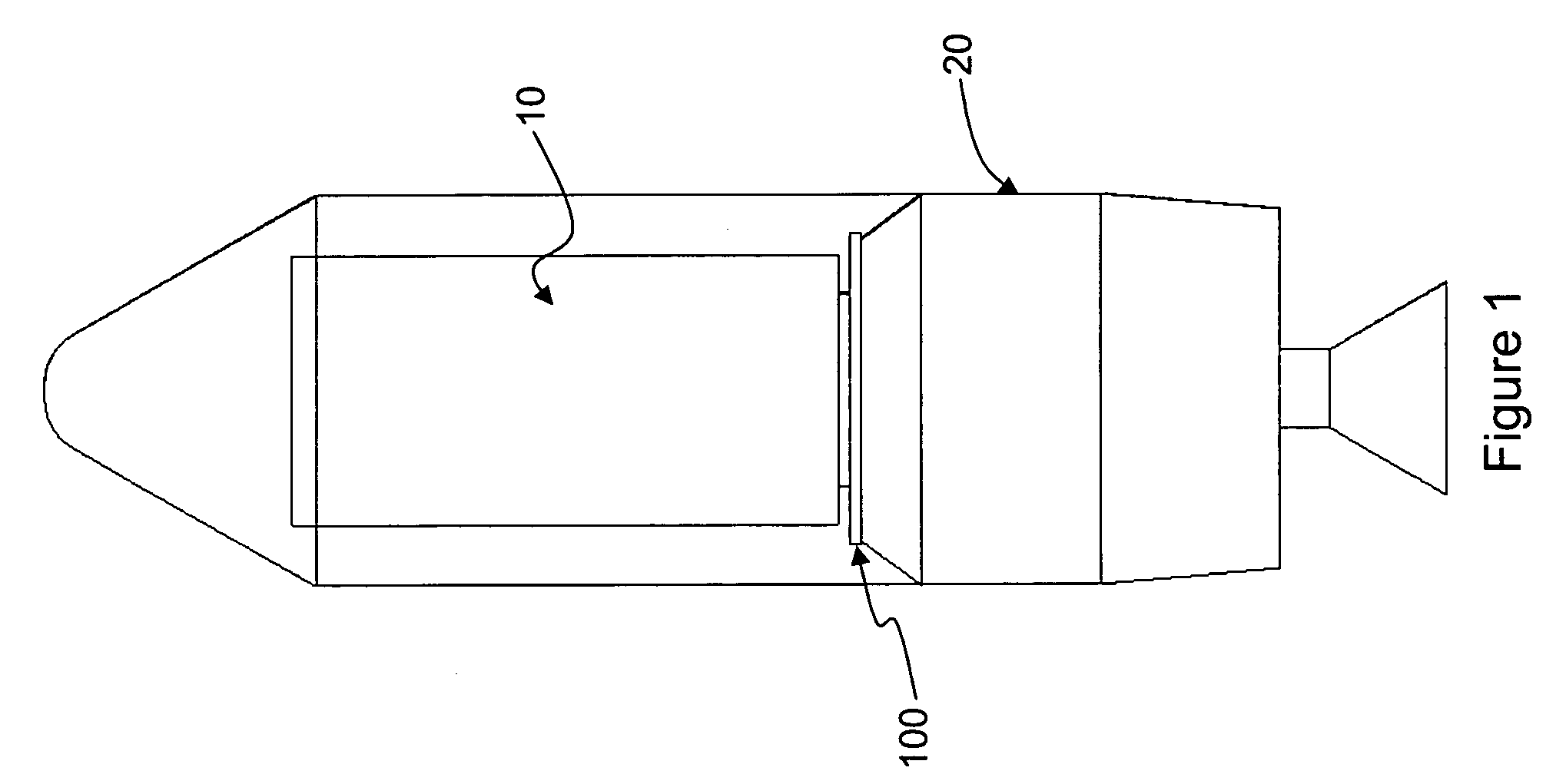
a payload adapter and payload technology, applied in the field of payload adapters, can solve the problems of fatigue damage and failure of sensitive payload components, axial components of the interface force between the payload and the satellite or spacecraft, and the payload is subject to severe vibration during flight,

Inactive Publication Date: 2007-05-29
ATA ENG
View PDF31 Cites 14 Cited by
  • Summary
  • Abstract
  • Description
  • Claims
  • Application Information

AI Technical Summary

Benefits of technology

[0012]A payload adapter configured in accordance with the invention achieves vibration isolation by minimizing the ratio of axial frequency to lateral frequency. The payload adapter can be designed in a manner that does not require a significant amount of customization related to the specific payload and / or launch vehicle specifications. In addition, the payload adapter need not employ add-on features, e.g., springs or other vibration damping elements.

Problems solved by technology

Payloads, such as satellites or spacecraft, which are mounted on launch vehicles, are subject to severe vibrations during flight.
The vibrations are often associated with severe quasi-static loads caused by axial thrust.
A direct result of the severe vibrations generally experienced by payloads is that fatigue damage and failure can be incurred by sensitive payload components.
This configuration leads to axial components of the interface forces between the payload and vehicle even in the presence of purely lateral loads.
This approach is not cost or weight efficient for a fragile payload and the concept of complete payload isolation is now widely adopted in such situations.
The real challenge in the design of a satisfactory complete payload vibration isolation system is to satisfy two competing requirements.
The lateral modes of vibration of the payload make the frequency requirements even more difficult to satisfy.
It is noted that if discrete springs are used to introduce flexibility into the payload mounting system it is difficult to avoid having the bounce mode higher than three times the lateral frequency.

Method used


Image

  • Payload adapter
  • Payload adapter
  • Payload adapter

Examples


Embodiment Construction

[0028]Embodiments of the invention will now be described with reference to the accompanying figures, wherein like reference numerals refer to like elements throughout. Unless otherwise expressly stated herein, the terminology used in the description presented herein is not intended to be interpreted in any limited or restrictive manner, simply because it is being utilized in conjunction with a detailed description of certain specific embodiments of the invention. Furthermore, embodiments of the invention may include several novel features, no single one of which is solely responsible for its desirable attributes or which is essential to practicing the inventions herein described.

[0029]As used herein, the terms “comprises,”“comprising,”“includes,”“including,”“has,”“having” or any other variation thereof, are intended to cover a non-exclusive inclusion. For example, a process, method, article, or apparatus that comprises a list of elements is not necessarily limited to only those elem...


PUM


Abstract

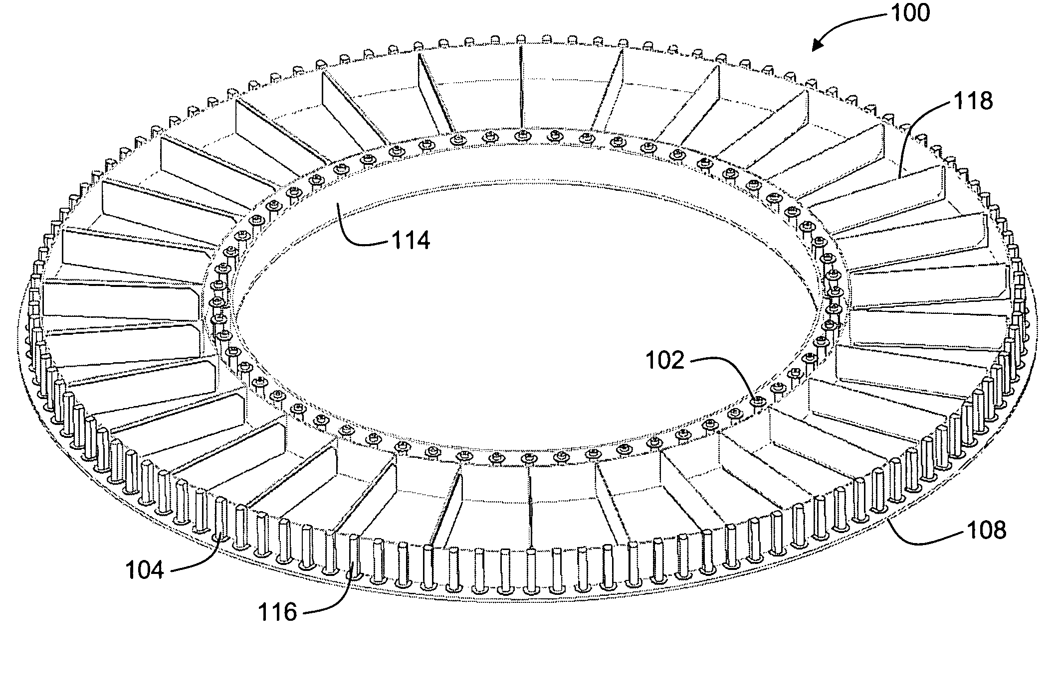
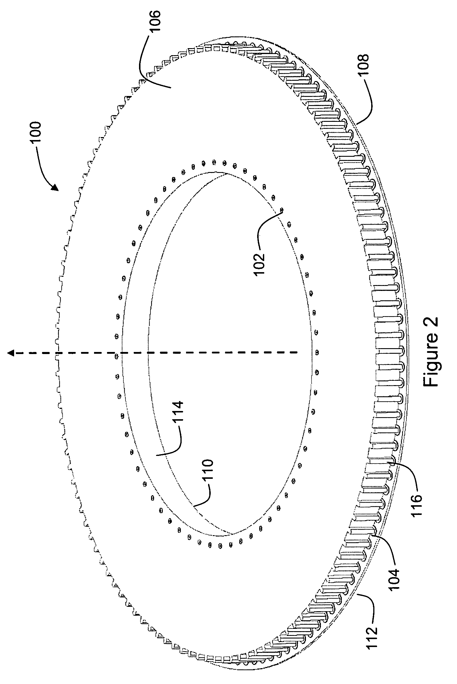
A payload adapter consists of a body that when hollow includes a plurality of stiffeners—radial and / or circumferential—or alternatively a core for carrying shear loads. The body may include a first annular face sheet, a second annular face sheet and a plurality of stiffeners connecting between the first annular face sheet and the second annular face sheet. The combination of the annular hollow body and the plurality of stiffeners or the same face sheets combined with an in-filled core results in an axial frequency and a lateral (pitch) frequency for the payload adapter that provides superior vibration isolation. Constrained layer damping is incorporated into the design for additional vibration attenuation.

Description

STATEMENT REGARDING FEDERALLY SPONSORED RESEARCH OR DEVELOPMENT[0001]This invention was made with United States Government support under contract F29601-02-C-0096 awarded by AFRL / PK8VV. The U.S. Government has certain rights in this invention.FIELD OF THE INVENTION[0002]The present invention relates generally to a payload adapter. More particularly, the present invention relates to a payload adapter that provides a convenient and integral mounting system to reduce the payload axial and lateral vibrations by keeping the associated natural frequencies as low as possible without affecting the launch vehicle controllability adversely.BACKGROUND OF THE INVENTION[0003]Payloads, such as satellites or spacecraft, which are mounted on launch vehicles, are subject to severe vibrations during flight. These vibrations are induced by multiple sources from liftoff to the instant of final separation from the launch vehicle. The dynamic mechanisms include ignition and operation of the rocket engine...

Claims


Application Information

Patent Timeline
Patent Type & Authority Patents(United States)
IPC IPC(8): B64G1/22
CPCB64G1/641
Inventor THOMAS, GARETH RHYSFADICK, CYNTHIA MARIE
Owner ATA ENG
Learn More