Identification and location system for personnel and vehicles

a technology for identifying and positioning agents, which is applied in the field of surveillance systems, can solve the problems of prior art methods that are not practical for use in a surveillance system designed, the location accuracy of the replying agent is limited to the accuracy of a gps receiver operating autonomously, and the surveillance system cannot achieve a detailed identification of each detected targ

Inactive Publication Date: 2007-05-29
FLIR SURVEILLANCE
View PDF10 Cites 8 Cited by
  • Summary
  • Abstract
  • Description
  • Claims
  • Application Information

AI Technical Summary

Benefits of technology

[0009]The present invention provides a new and improved method for detecting the presence of vehicles and personnel within a secured area, and for determining if a detected target is a “friend” or “foe”. It is an advantage of the present invention that the IFF unit carried by each authorized entity is light in weight and consumes a relatively small amount of power, thus minimizing the weight of the included batteries. It is also an advantage of the present invention that each IFF unit is capable of uniquely identifying the authorized person to which it is assigned, as well as its GPS derived position, velocity and direction of movement. It is still another advantage of the present invention that the only additional equipment that is required at the site of the surveillance radar is a GPS receiver and a data communication unit. This data communication unit receives identification and position data from the IFF units, and transmits IFF unit data and surveillance radar detection data to a processing facility. The processing facility has means to display a depiction of both the physical features of the secured area and the location and identification of each authorized entity. Any additional targets detected and displayed can be assumed to be hostile entities.
[0010]An additional advantage of the present invention is that computation of the range and bearing from the GPS receiver located at the radar to each of the IFF units allows determination of the IFF unit position from the radar to an accuracy of substantially one square meter.
[0011]The IFF unit includes a GPS receiver, a radar receiver, a memory module containing identification data unique to that unit, and a communication link transmitter. As the radar scans the secured area, the main beam briefly impinges upon each IFF unit. The radar receiver determines when the main beam event occurs and commands the communication link transmitter to transmit message containing the unit's identification and GPS derived coordinates. The present invention makes maximum use of commercially available, off the shelf subsystems, including the GPS receivers, the communication link transmitters within the IFF units, the surveillance radar, the data communication unit, and a personal computer for data processing and the radar display. This use of commercially available subsystems keeps the overall cost of the present invention to a minimum, as well as minimum size and powerconsumption of subsystems included in the IFF units.

Problems solved by technology

These sensors may use detection methods, and may operate over distances and in environmental conditions that make it impossible for the surveillance system to achieve a detailed identification of each detected target.
“Unfriendly” targets are not authorized to be in the area and thus are assumed to be hostile.
These prior art methods are not practical for use in a surveillance system designed to detect personnel and vehicles within sensitive areas having typical dimensions of no more than a few kilometers.
This data communication network can determine the GPS coordinates of all participating agents, but the location accuracy of the replying agent is limited to the accuracy of a GPS receiver operating autonomously.
These prior art examples have several limitations if an attempt is made to apply them for both detection of unauthorized intruders and identification of authorized entities within a secured area having dimensions of no more than a few kilometers.
The IFF units are not easily reconfigured as man carried, low power consumption devices that typically operate at a range in the order of a kilometer from the surveillance radar.

Method used


Image

  • Identification and location system for personnel and vehicles
  • Identification and location system for personnel and vehicles
  • Identification and location system for personnel and vehicles

Examples


Embodiment Construction

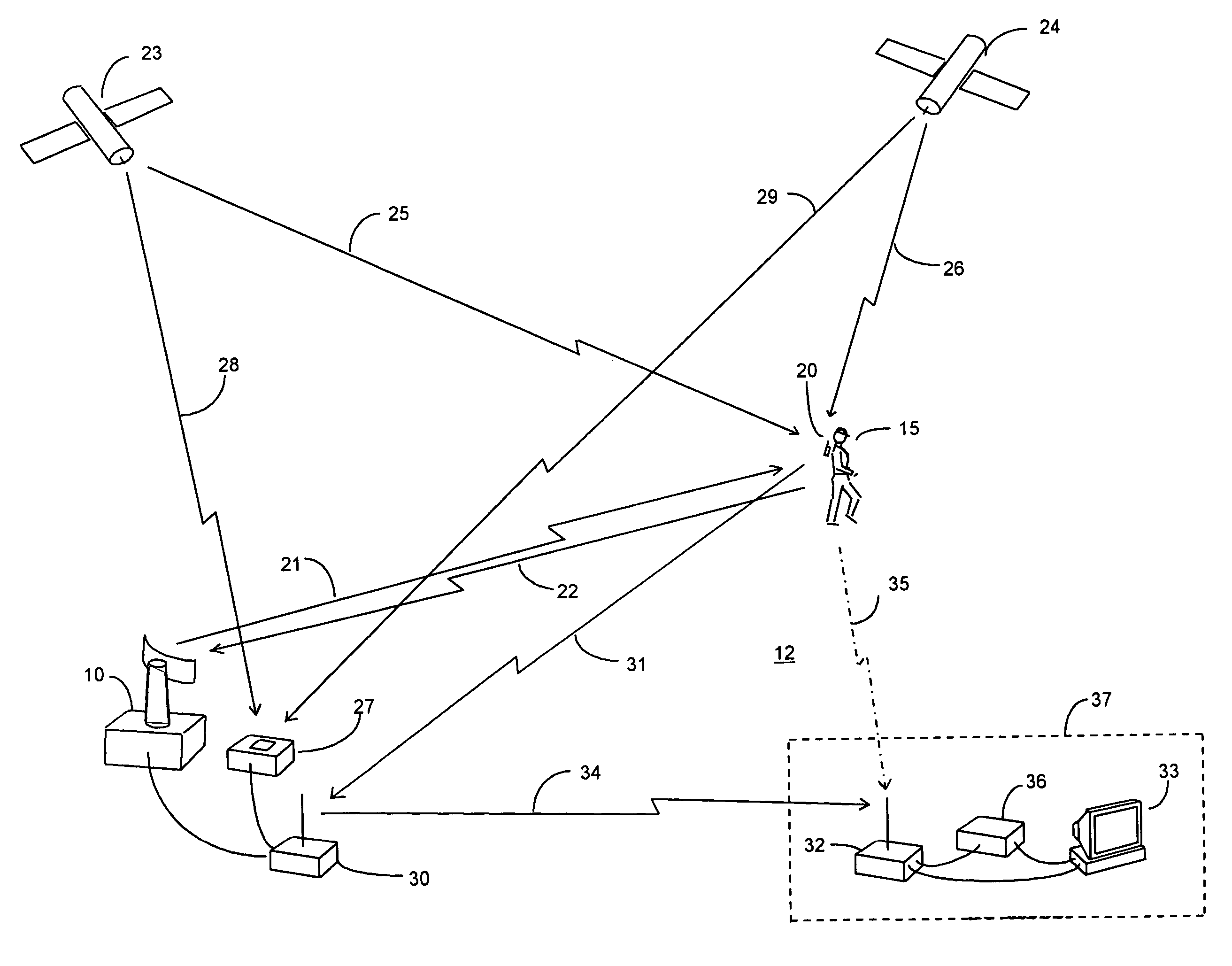
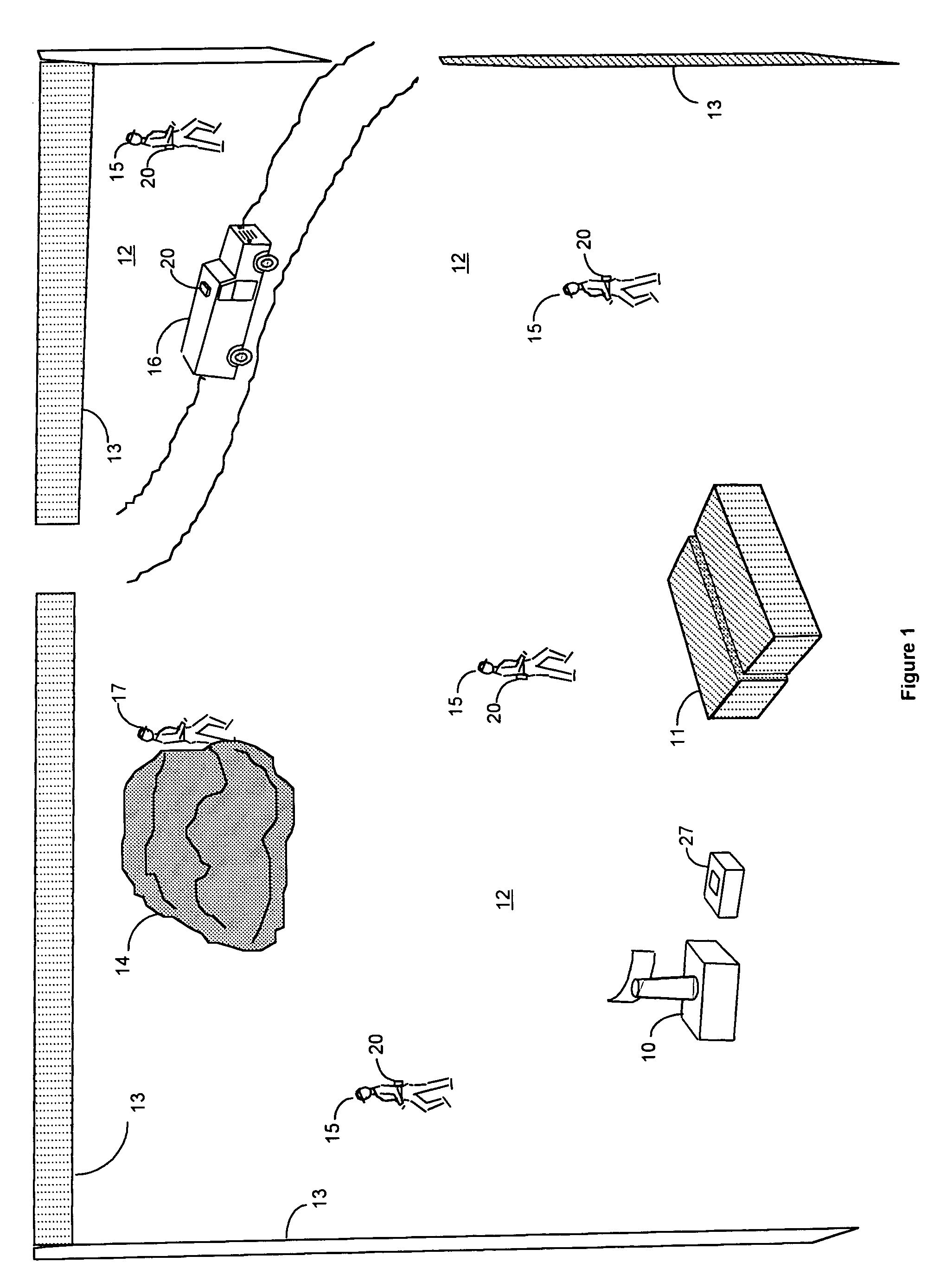
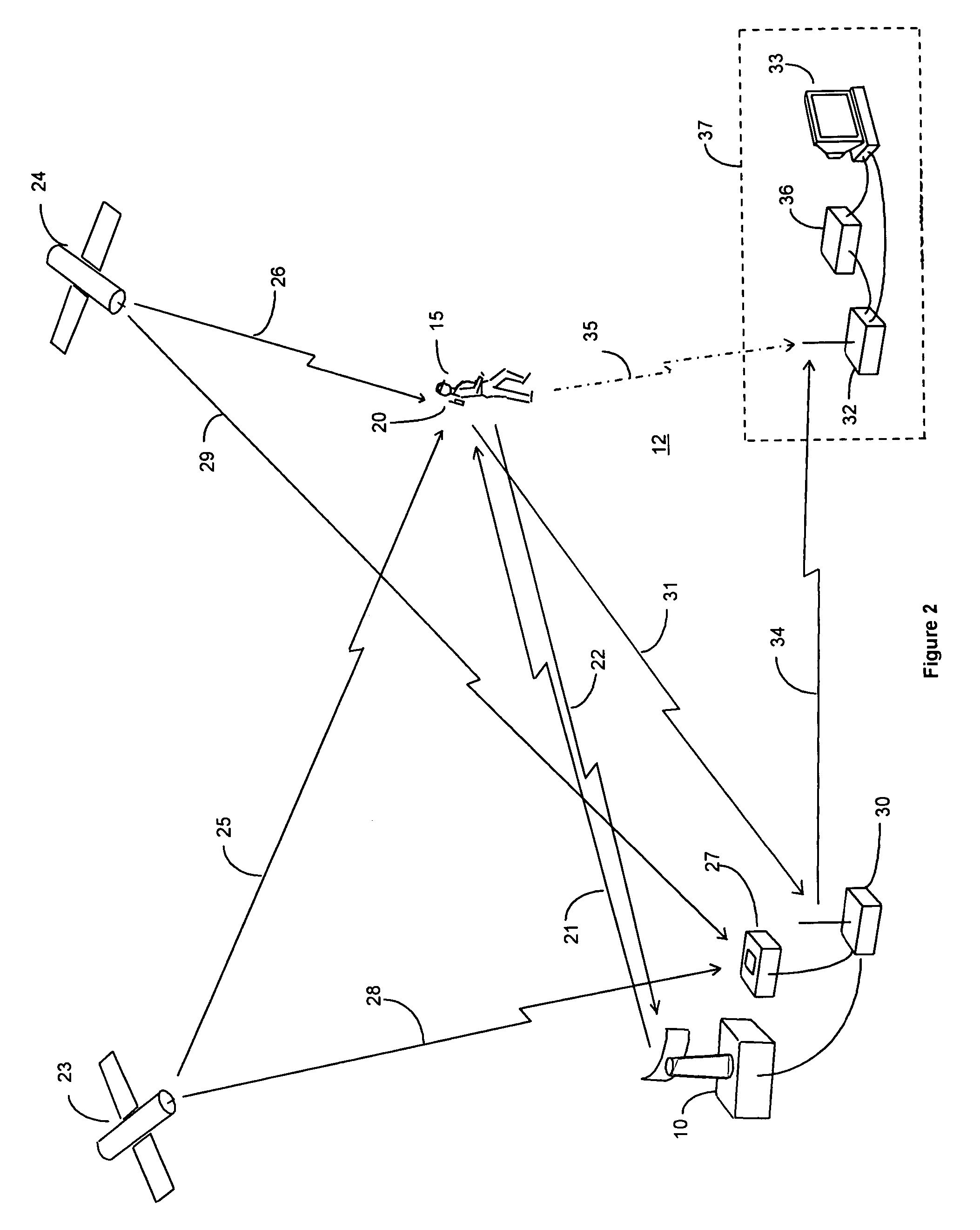
[0021]An example of a surveillance system of the present invention deployed to protect a sensitive area is shown in FIG. 1. The surveillance sensor 10 is implemented as a millimeter wave surveillance radar. Containers 11 are depicted as examples of high value assets in need of protection. These containers 11 are located within a secured area 12, defined by the fence 13. Although a fence is shown, the surveillance sensor 10 makes it possible to protect the secured area 12 without the requirement for a surrounding fence. The surveillance sensor 10 has a detection range sufficient to surveil the entire secured area 12, and is typically equipped with a rotationally scanning antenna that provides coverage of the entire secured area 12 including the area surrounding the containers 11. The secured area 12 may include terrain features, such as the rock formation 14, or man made structures (not shown) that generate fixed position returns for the surveillance sensor 10.

[0022]Multiple “friendl...


PUM


Abstract

A surveillance system is provided for surveillance of objects within a secure area. A surveillance sensor transmits surveillance signals to all objects within the secure area, the reflections of which are received back by the surveillance sensor to determine the locations of objects, and communicates the determined locations to a pressing facility. Objects authorized to be in the secure area are equipped with an Identification Friend or Foe (IFF) unit that includes a GPS receiver and a data communication transmitter. In response to predetermined conditions, the IFF units broadcast their position and identification to the processing facility for correlation with locations defined by the reflection signals. The reflection signals from other objects are compared with a list of the locations of objects, such as terrain features and man-made facilities, that are known to be in the secure area If no broadcast information is received from an object and the location of that object determined by the reflection signal cannot be correlated with the known object list; than the object has no proper authorization to be within the secure area, and an alarm is generated.

Description

CROSS-REFERENCE TO RELATED APPLICATIONS[0001]This application is a Continuation-In-Part (CIP) of application Ser. No. 10 / 430,167, now pending, filed May 6, 2003 now U.S. Pat. No. 6,816,106, the entire disclosure of which is incorporated herein by reference.BACKGROUND OF THE INVENTION[0002](1) Field of the Invention[0003]The present invention relates generally to surveillance systems, and in particular to a surveillance system used in conjunction with a device to provide location and identification of friendly personnel or vehicle targets.[0004](2) Description of Related Art[0005]Surveillance systems for the detection of personnel and vehicles within sensitive or secured areas are being deployed in significant numbers due to increased concern for security and also due to the availability of effective, affordable sensors. These sensors may use detection methods, and may operate over distances and in environmental conditions that make it impossible for the surveillance system to achiev...

Claims


Application Information

Patent Timeline
Patent Type & Authority Patents(United States)
IPC IPC(8): G01S13/78G01S19/35
CPCG01S5/0027G01S13/04G01S13/767G01S13/781G01S13/86
Inventor BUTLER, WALKERCHASE, CHARLES
Owner FLIR SURVEILLANCE
Why Eureka
Try Eureka