Preceding-vehicle detecting apparatus, own-vehicle controlling apparatus, and preceding-vehicle detecting method

a technology of preceding vehicles and detecting devices, which is applied in the direction of using reradiation, pedestrian/occupant safety arrangements, instruments, etc., can solve the problems of inability to fully eliminate noise, inability to detect vehicles, and the possibility of failing to detect preceding vehicles

Inactive Publication Date: 2007-05-29
NISSAN MOTOR CO LTD
View PDF25 Cites 13 Cited by
  • Summary
  • Abstract
  • Description
  • Claims
  • Application Information

AI Technical Summary

Problems solved by technology

However, the technique of JP-A-2001-242242, employing no more than three kinds of filters, has a potential failure to fully eliminate noises, with a resultant failure to detect a preceding vehicle.
It however is impossible to detect the vehicle by the technique of JP-A-2001-242242 in which such measuring-target points are all concluded to be noises.
From this point also, the technique of JP-A-2001-242242 has the possibility of failing to detect a preceding vehicle.

Method used


Image

  • Preceding-vehicle detecting apparatus, own-vehicle controlling apparatus, and preceding-vehicle detecting method
  • Preceding-vehicle detecting apparatus, own-vehicle controlling apparatus, and preceding-vehicle detecting method
  • Preceding-vehicle detecting apparatus, own-vehicle controlling apparatus, and preceding-vehicle detecting method

Examples


first embodiment

[0035](First Embodiment)

[0036]There will be described below a first embodiment of the invention with reference to accompanying drawings.

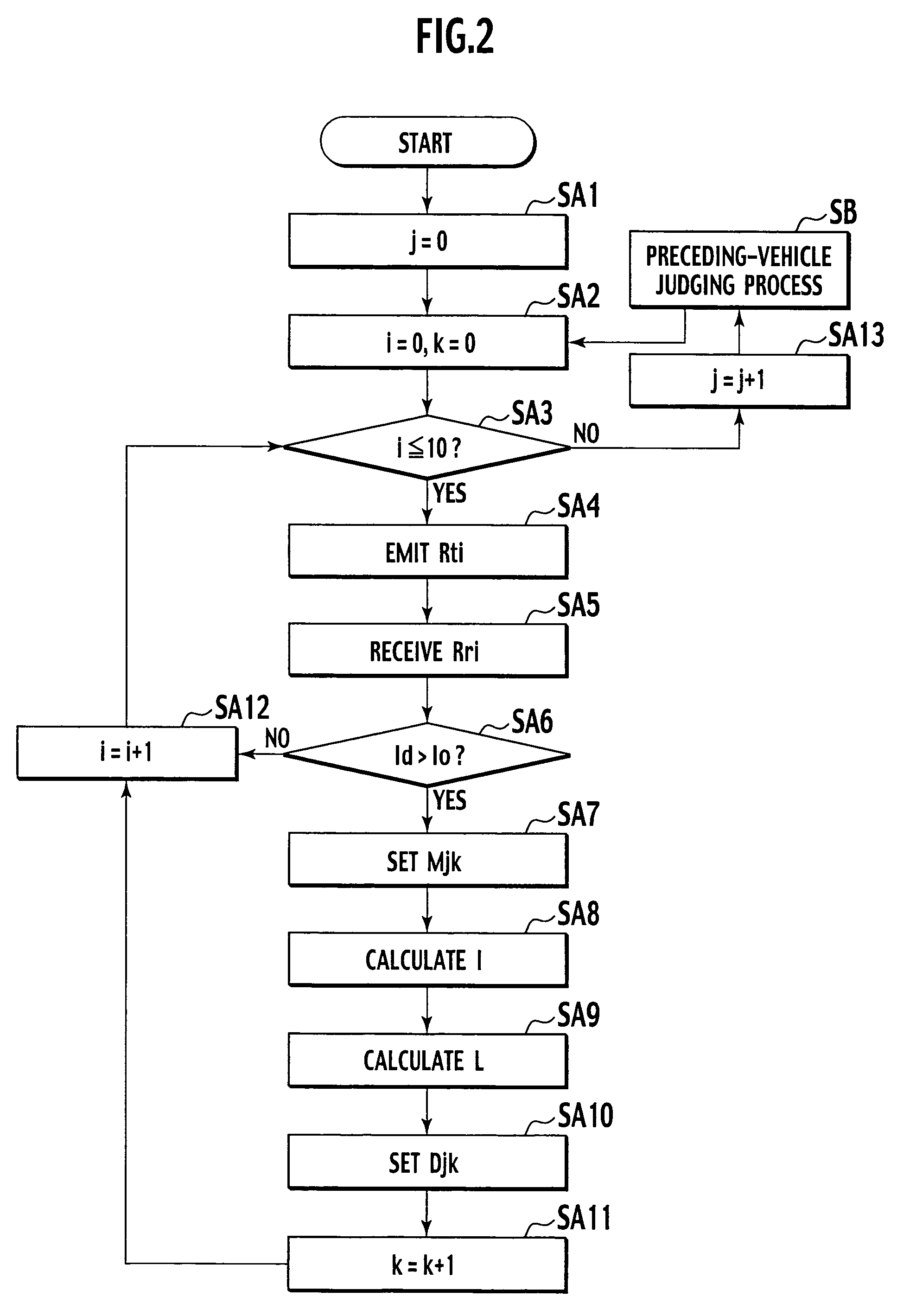
[0037]Description is first made, with reference to FIG. 1 through FIG. 5, of an outline of procedures to be conducted by a preceding vehicle detector as a preceding-vehicle detecting apparatus 1 according to the first embodiment.

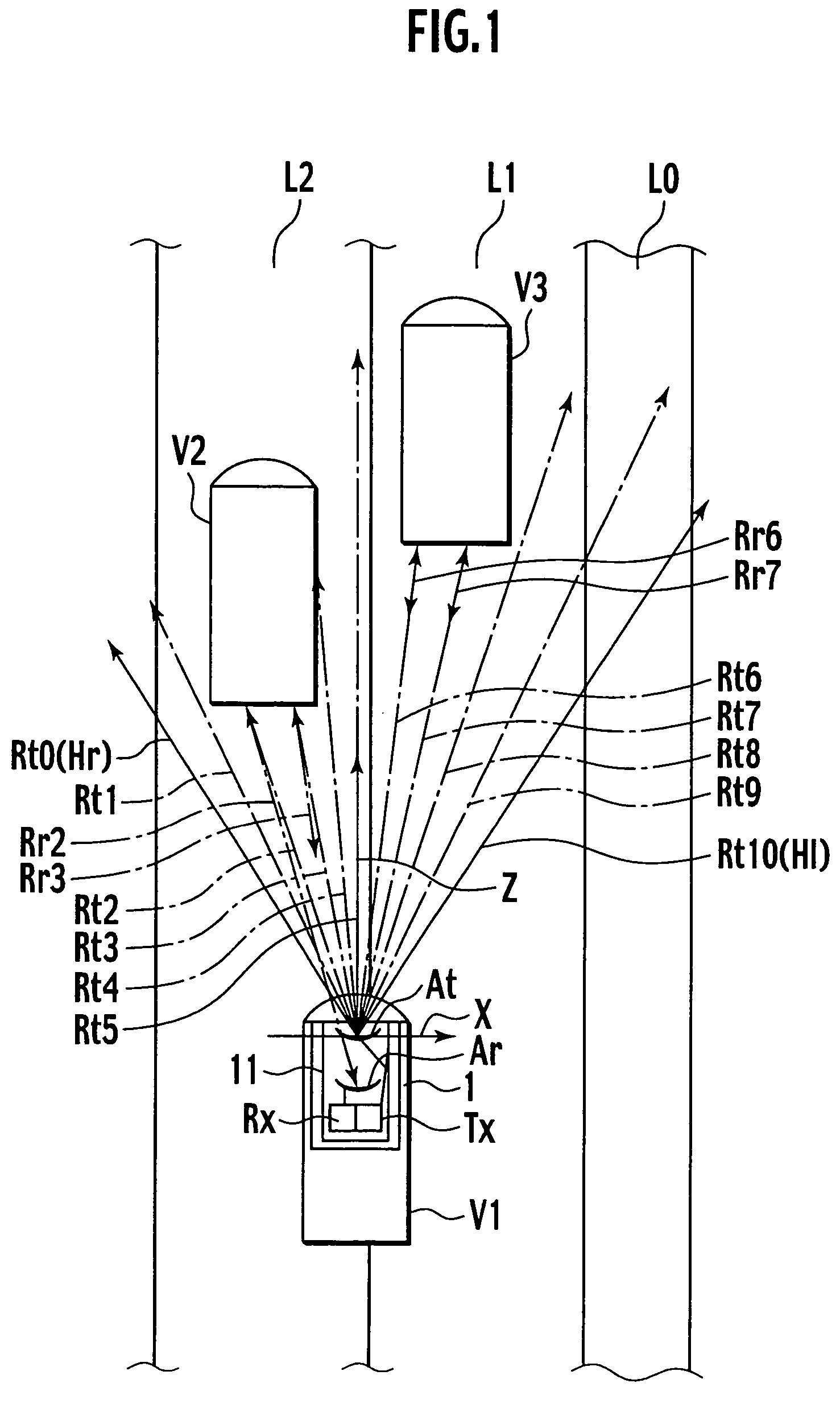
[0038]FIG. 1 is a plan view of an exemplary situation of an expressway, about an own vehicle V1. Alongside a median strip L0, a left overtaking lane L1 and a left cruising lane L2 extend. A preceding vehicle V2 runs in the overtaking lane L1, and another preceding vehicle V3 runs in the cruising lane L2. Running after vehicles V2 and V3 is the own vehicle V1, which is equipped with the preceding-vehicle detecting apparatus 1. The apparatus 1 includes a millimeter wave radar 11, which is configured with a transmitter as a transmitting part Tx and a receiver as a receiving part Rx. The transmitting part Tx has a transmitting a...

second embodiment

[0089](Second Embodiment)

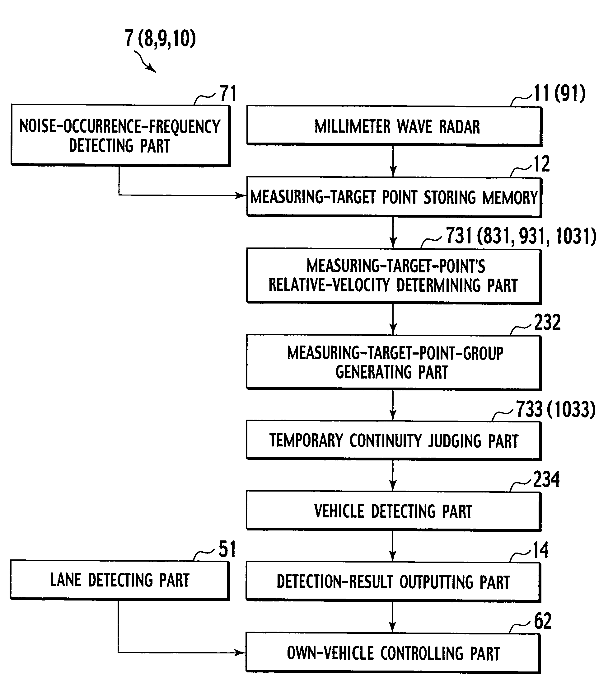
[0090]There will be described below a second embodiment of the present invention based on the drawings. There will be firstly described a configuration and constituent elements of a preceding-vehicle detecting apparatus 2 according to the second embodiment, with reference to FIG. 6, FIG. 8 through FIG. 10, FIG. 13 and FIG. 14. Here, FIG. 13 is a block diagram showing the configuration of the preceding-vehicle detecting apparatus 2, and FIG. 14 is a schematic plan view showing positions of measuring-target points.

[0091]As shown FIG. 6 and FIG. 8, the preceding-vehicle detecting apparatus 2 is mounted on an own vehicle P, and is provided by substituting the data processor 13 of the preceding-vehicle detecting apparatus 1 by a data processor 23. As shown in FIG. 13, the data processor 23 comprises a measuring-target-point relative-velocity determining part 231, a measuring-target-point-group generating part 232, a temporal continuity judging part 233, and a veh...

third embodiment

[0106](Third Embodiment)

[0107]There will be described below a third embodiment of the present invention based on the drawings. There will be firstly described a configuration and constituent elements of a preceding-vehicle detecting apparatus 3 according to the third embodiment, with reference to FIG. 6, FIG. 8, FIG. 13 and FIG. 16 through FIG. 17. Here, FIG. 13 is a block diagram showing the configuration of the preceding-vehicle detecting apparatus 3, and FIG. 16 through FIG. 17 are graphs each showing a relationship between: a time point (abscissa); and a Z-coordinate value of a pertinent measuring-target point group detected at each time point.

[0108]As shown FIG. 6 and FIG. 8, the preceding-vehicle detecting apparatus 3 is mounted on an own vehicle P, and is provided by substituting the data processor 23 of the preceding-vehicle detecting apparatus 2 by a data processor 33. As shown in FIG. 13, the data processor 33 is provided by substituting the temporal continuity judging par...


PUM


Abstract

To provide a preceding-vehicle detecting apparatus, own-vehicle controlling apparatus and preceding-vehicle detecting method capable of detecting a preceding vehicle in a more reliable manner, a preceding-vehicle detecting apparatus (1) comprises: a millimeter wave radar (11); a measuring-target-point-group generating part (131) setting measuring-target points based on reflected waves, and single-connecting those measuring-target points having the same relative velocities to thereby generate measuring-target point groups, respectively; a group-relative-velocity determining part (132) extracting those measuring-target point groups which meets conditions for preceding vehicle, respectively; and a temporal continuity judging part (133) regarding those measuring-target point groups as preceding vehicles, each of which has a number of detected times equal to or larger than a prescribed value (N1).

Description

BACKGROUND OF THE INVENTION[0001]1. Technical Field[0002]The present invention relates to a preceding-vehicle detecting apparatus, an own-vehicle controlling apparatus, and a preceding-vehicle detecting method.[0003]2. Background Art[0004]JP-A-2001-242242 has disclosed a technique for detecting a preceding vehicle. As used herein, the term “preceding vehicle” means a vehicle preceding an own vehicle.[0005]The technique of JP-A-2001-242242 employs a millimeter wave radar adapted to emit millimeter waves in a forward direction of own vehicle, and receive reflected waves thereof. Based on the reflected waves, measuring-target points are set, and positions and relative velocities of the measuring-target points are calculated. A phase space corresponding to a detecting region is divided into three, and a filter is set for each divided region. Each measuring-target point is applied to a filter corresponding thereto in position, where noises are eliminated. Remaining measuring points have ...

Claims


Application Information

Patent Timeline
Patent Type & Authority Patents(United States)
IPC IPC(8): G01S13/93B60R21/00G01S13/931G01S7/02G01S13/72G01S13/86G08G1/16
CPCG01S13/931G01S13/726G01S13/867G01S2013/9375G01S2013/9325G01S2013/9339G01S2013/9353G01S2013/9357G01S2013/9322G01S2013/9329G01S2013/93271G01S2013/932
Inventor SHIMOMURA, NORIKO
Owner NISSAN MOTOR CO LTD
Why Eureka
Try Eureka