RF transceiver having a directly radiating transistor

a technology of rf transceivers and transistors, applied in the field of microwave transceivers, can solve the problems of device limitations, device packages are limited rather than transistor limitations, and limit operation beyond 18 ghz

Inactive Publication Date: 2007-05-29
MCEWAN TECH
View PDF21 Cites 29 Cited by
  • Summary
  • Abstract
  • Description
  • Claims
  • Application Information

AI Technical Summary

Benefits of technology

[0014]In one embodiment, a system based on the teachings contained herein may be configured to provide millimeter-wave and near millimeter-wave radar sensors using low-cost packaged transistors.

Problems solved by technology

Such devices may be limited by package parasitics such as inductance and wavelength effects on the package leads.
Package parasitics seriously limit operation beyond 18 GHz; the device is package-limited rather than transistor-limited.
The prior art does not teach how to employ package-limited devices in transceiver applications at frequencies beyond cutoff.
Unfortunately, it is nearly impossible to operate a transistor at such high frequencies that its leads are one-quarter wave long, i.e. at package limited frequencies.

Method used


Image

  • RF transceiver having a directly radiating transistor
  • RF transceiver having a directly radiating transistor
  • RF transceiver having a directly radiating transistor

Examples


Embodiment Construction

[0020]A detailed description of the present invention is provided below with reference to the figures. While illustrative component values and circuit configurations are given, other embodiments can be constructed with other component values and circuit configurations. All U.S. patents cited herein are herein incorporated by reference.

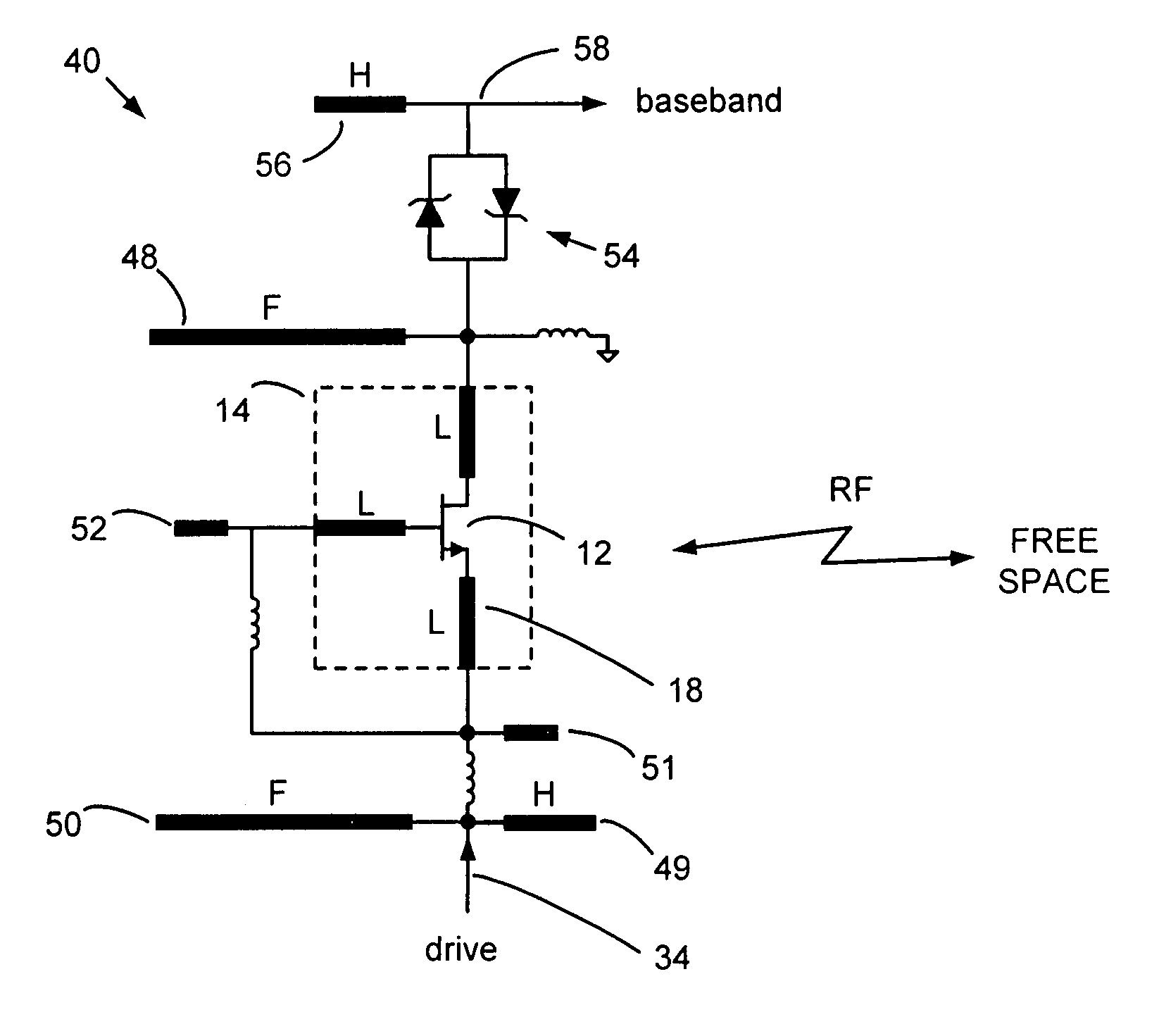
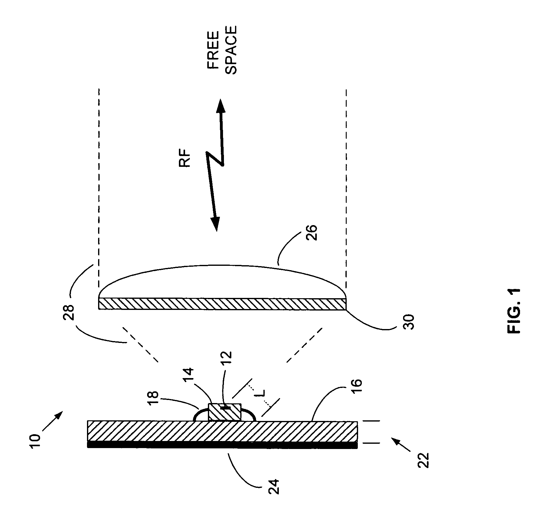
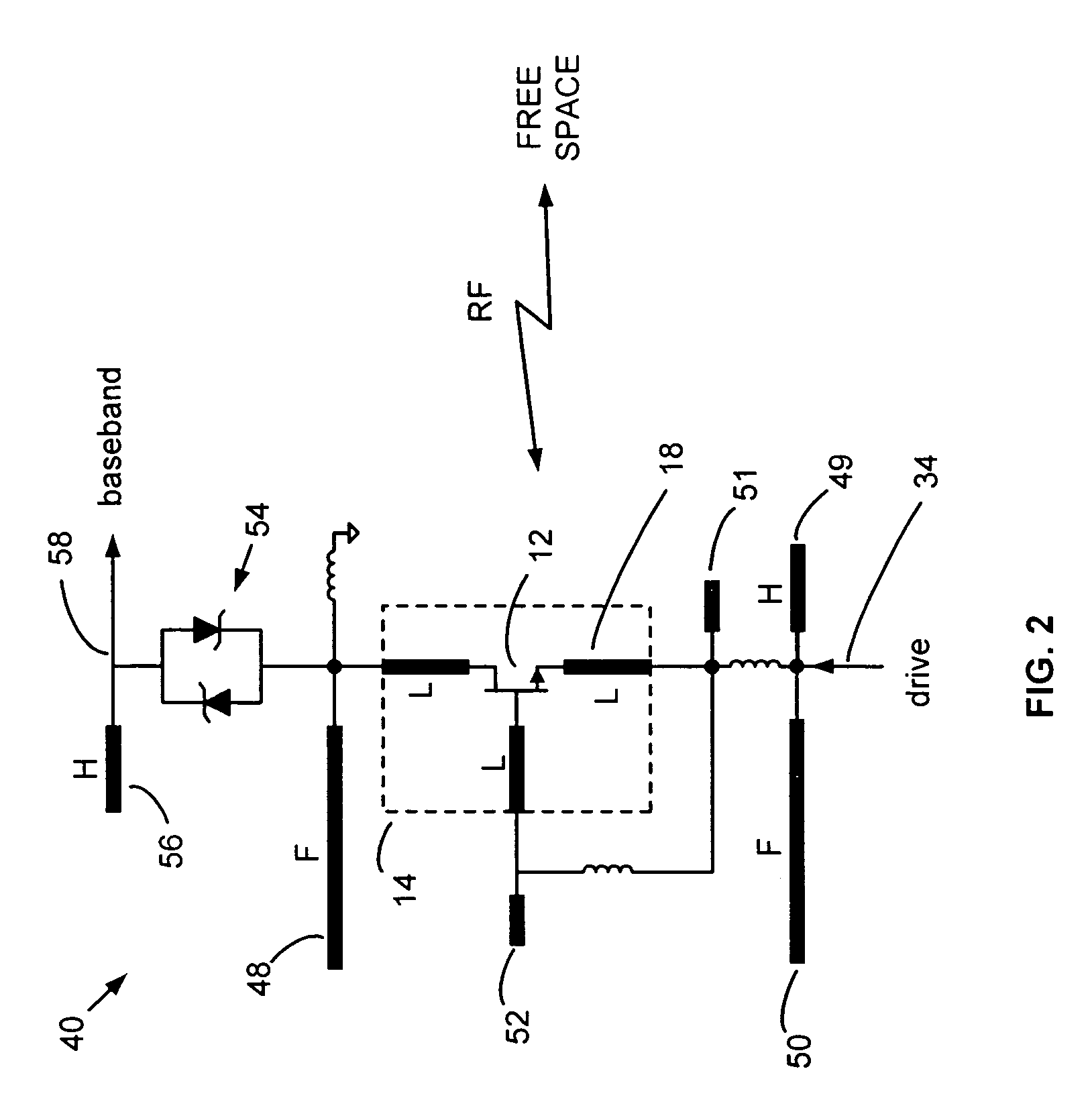
[0021]FIG. 1 is a block diagram of a microwave transceiver 10 of the present invention. Although shown as a transceiver, it is contemplated that the transceiver may comprise a device configured to perform only a transmit function, receive function, or both. A transistor die 12 is enclosed in package 14 and connected to substrate 16 via lead 18. The embodiments shown herein refer primarily to a transistor or transistor die, however, it is contemplated that in devices, circuits or systems other than a transistor may be utilized. Thus, the claims that follow should not be limited to a transistor or transistor die. Reference to lead 18 generally refers to ...


PUM


Abstract

Transistor package leads form quarter-wave antenna elements that directly radiate RF energy into free space without the need for a separate antenna. The transistor operates at a fundamental frequency and radiates a harmonic, thereby allowing radiation at frequencies normally considered “beyond cutoff” for a packaged transistor. This technique enables an additional 20 GHz of spectrum for use by surface mount technology. The transistor may be mounted on 1.6 mm thick glass-epoxy circuit board that also forms a quarter-wave reflector at 26 GHz. An optional dielectric lens produces a narrow beam and an optional planar filter rejects spurious fundamental emissions. A 26 GHz ultra-wideband (UWB) pulse-echo radar rangefinder implementation provides a low-cost upgrade to ultrasound.

Description

BACKGROUND OF THE INVENTION[0001]1. Field of the Invention[0002]The present invention relates to microwave transceivers, and more particularly to microwave radar sensors, such as rangefinders and motion detectors.[0003]2. Description of Related Art[0004]Radio and radar transceivers operate at radio frequency (RF) wavelengths that are larger than the active devices used to generate the RF. Active devices, such as vacuum tubes and transistors, are considered to be “beyond cutoff” when subjected to frequencies having a wavelength approaching their physical dimensions or the dimensions of their connection leads. Operation at such short wavelengths is nearly impossible since a quarter-wavelength lead forms a transformer that inverts the impedance from low to high or vice-versa. In contrast, antennas need to be a significant fraction of a wavelength, such as a quarter-wavelength, for efficient radiation into free space.[0005]Small inductors can radiate with limited effectiveness for appli...

Claims


Application Information

Patent Timeline
Patent Type & Authority Patents(United States)
IPC IPC(8): H04B1/40H01Q1/44H01Q9/16H01Q23/00H04B1/69
CPCH01Q1/44H01Q9/16H01Q23/00H04B1/71635
Inventor MCEWAN, THOMAS E.
Owner MCEWAN TECH
Why Eureka
Try Eureka