Machine tool, in particular a drilling and milling machine

a technology of machine tools and workpieces, which is applied in the direction of metal-working holders, positioning devices, supports, etc., can solve the problems of high cost, inability to reach bearings and drive means, and difficulty in machining residues such as chips, lubricants and coolants, and the movement apparatus, in particular for the workpiece table in high-precision milling machines, becomes very complex and expensiv

Active Publication Date: 2007-06-05
MIKRON AGIE CHARMILLES
View PDF14 Cites 34 Cited by
  • Summary
  • Abstract
  • Description
  • Claims
  • Application Information

AI Technical Summary

Benefits of technology

[0011]The presence of an automatic pallet changer allows the machining process to be significantly improved. The automatic pallet change can be used in serial machining for time-saving purposes.

Problems solved by technology

Machining residues, such as chips, lubricant and coolant, are unable to get to the bearings and drive means, or can do so only with difficulty.
The movement apparatus, in particular for the workpiece table in high-precision milling machines, thereby becomes very complex and expensive.
For a 5-axis machining, the workpiece table or the machining head must additionally be pivotably configured, which further increases the design complexity.
Also, for a 5-axis machining, either the machining head is pivotably configured in a constructionally complex manner, or the workpiece table mounted on a base wall of the machine stand must be pivotably configured, whereby, in the absence of complex and expensive sealing measures, there is the danger of machining residues, lubricant and coolant getting into the drive apparatus of the workpiece table.

Method used


Image

  • Machine tool, in particular a drilling and milling machine
  • Machine tool, in particular a drilling and milling machine
  • Machine tool, in particular a drilling and milling machine

Examples


Embodiment Construction

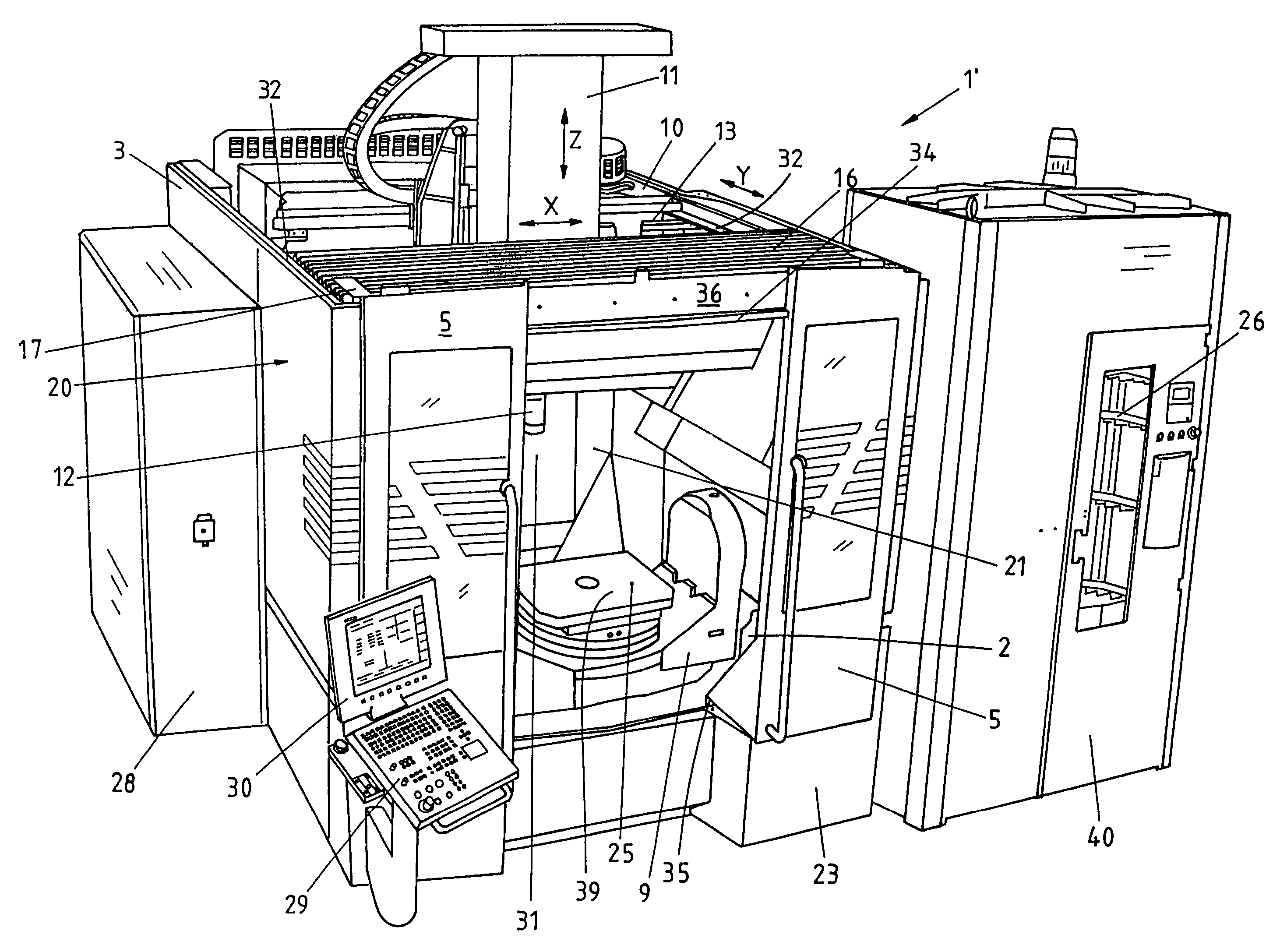
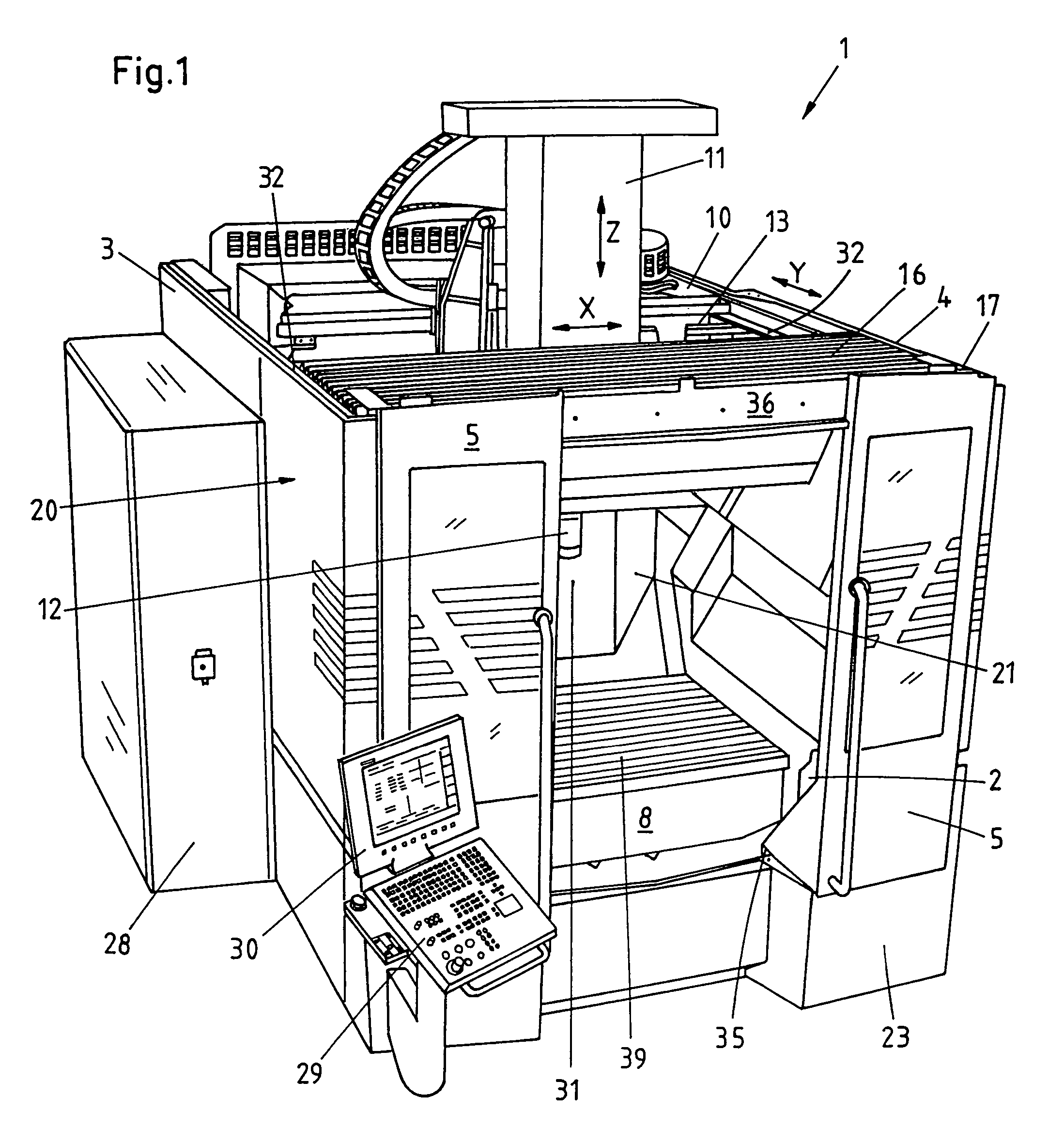
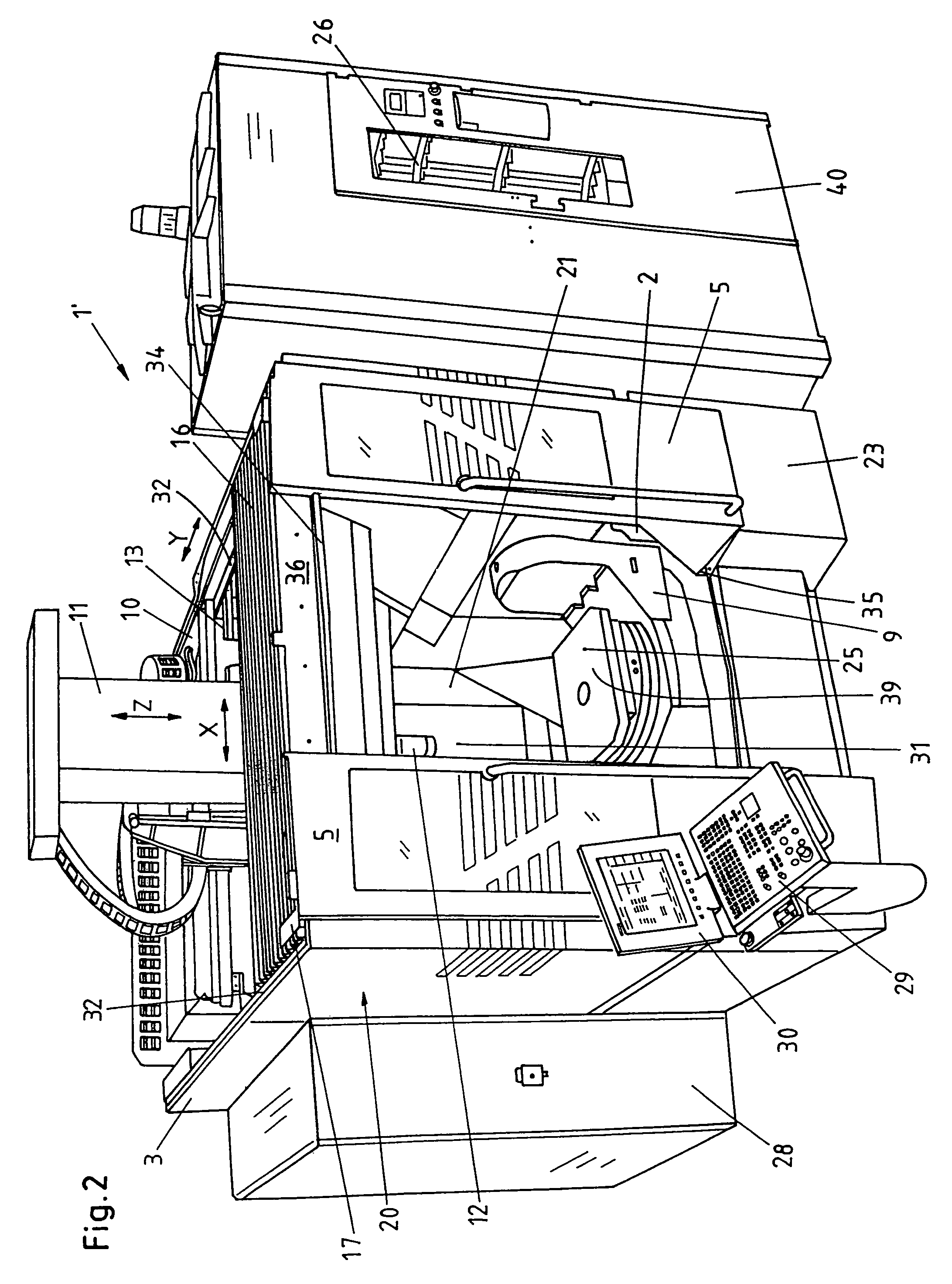
[0022]FIG. 1 shows a machine tool 1 in 3-axis construction. FIG. 2 shows a machine tool 1′ in 5-axis construction. The reference symbols of the two machines 1 and 1′ have the same meaning. The housing 20 comprises the side walls 3 and 4 and the front and rear door walls 23 and 31 containing the doors 5 and 6. The front door 5 is configured as a two-part sliding door, the door guides 35 lying in the lower region 39 of the front door wall 23 and the upper region 34 of the door wall 23 being free. A free loading area 21 for large-sized parts is thereby enabled. In the upper roof region 13, there is provided as a partial roof cover a concertina 16 together with the cross bar 36, which latter is detachably connected on the upper edge 17 of the front door side 23. The concertina 16 is folded or unfolded by means of the slide 10. The rear door 6 is configured as a tilt-up door and serves for the supply of pallets delivered by the automatic pallet changer 14 (not visible in FIGS. 1 and 2) d...


PUM

PropertyMeasurementUnit
areaaaaaaaaaaa
movementaaaaaaaaaa
poweraaaaaaaaaa

Abstract

A machine tool (1, 1′), in particular a drilling and milling machine, comprising a housing (20) having a machine bed (2), together with side walls (3, 4) and doors (5, 6, 7), comprising a fixed, pivotable or rotatable work table (8, 9), and comprising a slide (10), transportable in the y direction, for the reception of a spindle head (11), transportable in the x-z direction, for the reception of tools (12), wherein the front door (5), for the enlargement of the working and loading area (21) in the upward direction, is of transomless configuration, the roof region (13) of the machine (1, 1′) has an automatically operable cover (16), the rear region (22) of the machine (1, 1′) has an integrable automatic pallet changer (14), and the machine (1, 1′) is assigned an automatic tool changer (15).

Description

BACKGROUND OF THE INVENTION[0001]The invention relates to a machine tool, in particular a drilling and milling machine, comprising a housing having a machine bed, together with side walls and doors, comprising a fixed, pivotable or rotatable work table, and comprising a slide, transportable in the y direction, for the reception of a spindle head, transportable in the x-z direction, for the reception of tools.[0002]In EP 0 712 682, a machine tool, in particular a drilling and milling machine, is proposed, which is provided with a machine stand on which a motor-driven longitudinal slide, guided on guide rails, is horizontally movable. A machining head, which has a rotary drive apparatus for at least one tool, is movable on the longitudinal slide in at least one further motional direction by motor power. The machine stand has two spaced-apart side walls, on which the longitudinal slide is at least partially guided and the space between which is configured as a machining area. On each o...

Claims


Application Information

Patent Timeline
Patent Type & Authority Patents(United States)
IPC IPC(8): B23Q3/157B23Q11/08B23Q7/00
CPCB23Q1/012B23Q1/66B23Q11/0816B23Q11/0891Y10T483/115Y10T409/307728Y10T483/16Y10T409/30392Y10T409/305656Y10T29/5196
Inventor KONVICKA, JANREIMANN, MARKUS
Owner MIKRON AGIE CHARMILLES
Why Eureka
Try Eureka