Tack device with shield

a shield and tack technology, applied in the field of incontinence treatment methods and apparatus, can solve the problems of urinary incontinence being a common medical complaint, bare sutures can cut into and damage the urethra, and the knotting of sutures (after they are tightened) takes skill and tim

Inactive Publication Date: 2007-06-05
BOSTON SCI SCIMED INC
View PDF118 Cites 103 Cited by
  • Summary
  • Abstract
  • Description
  • Claims
  • Application Information

AI Technical Summary

Benefits of technology

[0026]An aspect of some preferred embodiments of the invention relates to an attachment to a bone stapler, which attachment holds a sling in place over a staple-exit portion of the stapler, to enable a standard stapler or a standard bone-anchor inserter to be used for tacking slings in accordance with a preferred embodiment of the invention. In a preferred embodiment of the invention, the type of stapler provided is such that the tip of the staple does not protrude from the stapler, so the sling is preferably maintained in place solely by the attachment. In an alternative embodiment, the tip of the staple does protrude from the stapler and may serve to at least partially hold the sling, while the attachment fixes the orientation of the sling relative to the staple or the attachment. If a two prong staple (or tack) is used, such an attachment may serve solely to keep the sling from slipping off the tip of the staple.

Problems solved by technology

Urinary incontinence is an unfortunately common medical complaint.
The disadvantage of these procedures is that the bare sutures can cut into and damage the urethra.
(a) the suture is an additional element which may be damaged during the procedure or after it;
(b) knotting the sutures (after they are tightened) takes skill and time; additionally, some patients have complained that the sutures cause discomfort during sexual activity, since such sutures typically have sharp edges and are often bulky as the suture may have to be knotted as many as six times to assure patency;
(c) the sutures add some unwanted leeway between the positioning of the anchors and the positioning of the ends of the sling; and
(d) the sutures may damage the sling by cutting through it (older tissue being more susceptible); if the suture enters the sling at multiple points (to reduce strain at the sling-suture joints) the sling may be deformed by the sutures.
However, this solution may not be suitable for some patients, such as older patients, as their tissue are usually too weak to provide a suitable support.
Also, older tissue is more susceptible to cut-through damage from the staples.

Method used


Image

  • Tack device with shield
  • Tack device with shield
  • Tack device with shield

Examples


Embodiment Construction

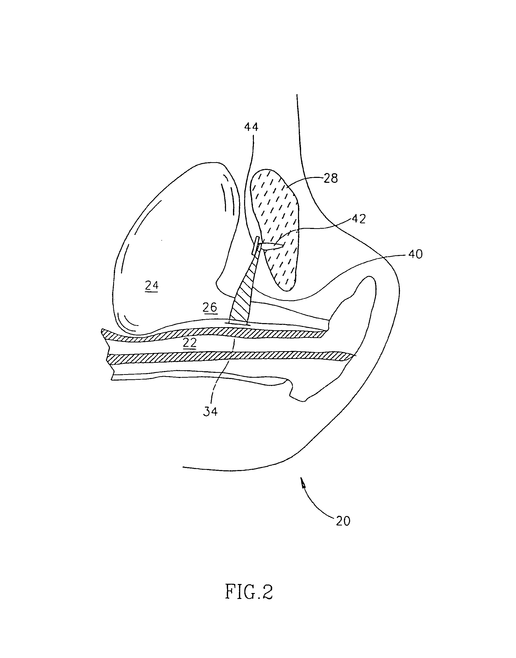
[0084]FIG. 2 is a schematic cut-through illustration of a pubic area during a bladder neck support operation, in accordance with a preferred embodiment of the invention. A sling 40 is shown as being tacked directly to pubic bone 28, by a tack 42 and being held in place by a head 44 of tack 42. In a preferred embodiment of the invention, a shaft of tack 42 pierces sling 40. Alternatively or additionally, the sling is held against the bone by friction, caused by head 44 urging sling 40 against pubic bone 28 (possibly through intervening tissue).

[0085]In a preferred embodiment of the invention, the following method is used to attach the sling to the bone:

[0086](a) a first tack is tacked (preferably through sling 40) into a first location on pubic bone 28;

[0087](b) the sling is inserted between vagina 22 and bladder neck 26 or the urethra: access is preferably via one or more incisions in the vaginal wall;

[0088](c) a second tack is tacked through the sling and into a second location on ...


PUM


Abstract

A slotted shield for a surgical tack, including a body adapted to engage a tack head. The shield has at least one slot having a width, defined by the body. Optionally, the shield is mounted on a tack head on which said shield is mounted.

Description

RELATED APPLICATIONS[0001]This application is a Divisional of U.S. patent application Ser. No. 09 / 684,108, filed Oct. 6, 2000 U.S. Pat. No. 6,544,273, which was a Continuation-In-Part (CIP) of U.S. patent application Ser. No. 09 / 475,870, filed Dec. 30, 1999, issued on May 14, 2002 as U.S. Pat. No. 6,387,041 which claims priority to Israeli patent application serial number 127978, filed Jan. 8, 1999, the disclosures of which are incorporated herein by reference.FIELD OF THE INVENTION[0002]The present invention relates to methods and apparatus for treating incontinence, especially by bladder neck support.BACKGROUND OF THE INVENTION[0003]Urinary incontinence is an unfortunately common medical complaint. Many treatments have been suggested. Recently, a relatively minimally invasive technique has become more common, in which a bladder neck and / or urethra is supported by a sling, so that the urethra is partially compressed and / or has a support below it so that during straining and / or blad...

Claims


Application Information

Patent Timeline
Patent Type & Authority Patents(United States)
IPC IPC(8): A61F13/00A61B17/00A61B17/58A61B17/04A61B17/064A61F2/00
CPCA61B17/0401A61F2/0045A61B17/0642A61B2017/00805A61B2017/00867A61B2017/0409A61B2017/0412A61B2017/0427A61B2017/0437A61B2017/044A61B2017/0647
Inventor HARAI, BOAZBEYAR, MORDECHAYGLOBERMAN, OREN
Owner BOSTON SCI SCIMED INC
Why Eureka
Try Eureka