Vehicle imaging system

a vehicle vision and control system technology, applied in the field of vehicle vision systems, can solve the problems of system bulk and cost, system deficiency in determining the distance between the sensed light source, and difficulty in reliably detecting taillights, so as to avoid excessive additional costs and bulk to the vehicle vision and/or control system, accurate determining the distance from the subject vehicl

Inactive Publication Date: 2007-06-05
MAGNA ELECTRONICS
View PDF146 Cites 337 Cited by
  • Summary
  • Abstract
  • Description
  • Claims
  • Application Information

AI Technical Summary

Benefits of technology

[0006]The present invention provides a vehicular imaging system which is capable of accurately determining the distance from the subject vehicle to an object or light source sensed by the sensors of the imaging system. The distance sensor accurately estimates the distance between the sensed object and the vehicle, while avoiding excessive additional costs and bulk to the vehicle vision and / or control system. In one aspect, the present invention is intended to provide a vehicular headlamp control system which senses oncoming headlights and leading taillights of other vehicles and controls the headlamps of the subject vehicle in response to the sensed light sources and the distance between the vehicle and the sensed light sources. The control system preferably includes ranging capability for determining the distance between the sensed objects and the vehicle. The device preferably is adaptable for use in other vehicular imaging systems associated with the vehicle which may display a distance readout to an operator of the vehicle or may control a vehicle accessory in response to the distance.

Problems solved by technology

While such devices provide distance information to the associated vehicular system, this requires an additional sensing device separate from the vehicular vision or camera system, which adds to the bulk and costs associated with the system.
However, these systems typically require a sufficiently low threshold of detection such that many other lower intensity light sources may also be interpreted as headlights or taillights.
These systems also have difficulties in reliably detecting taillights of other vehicles traveling ahead of the operative vehicle, since the intensity of taillights is typically substantially less than the intensity of oncoming headlights.
Such systems are deficient in determining the distance between the sensed light source and the subject vehicle, which would be helpful modulating the headlamps in response to both the sensed light and the distance to the light.
However, such a calculation is only accurate when the sensed light source intensity is within a predetermined level corresponding to a known or assumed intensity of headlamps and is at certain distances.
Because the intensity of headlamps and taillamps vary between vehicles and may further vary as the headlamps are modulated between high and low beams and as the brake lights are activated or deactivated, such an estimation of distance may be inaccurate in many cases.

Method used


Image

  • Vehicle imaging system
  • Vehicle imaging system
  • Vehicle imaging system

Examples


Embodiment Construction

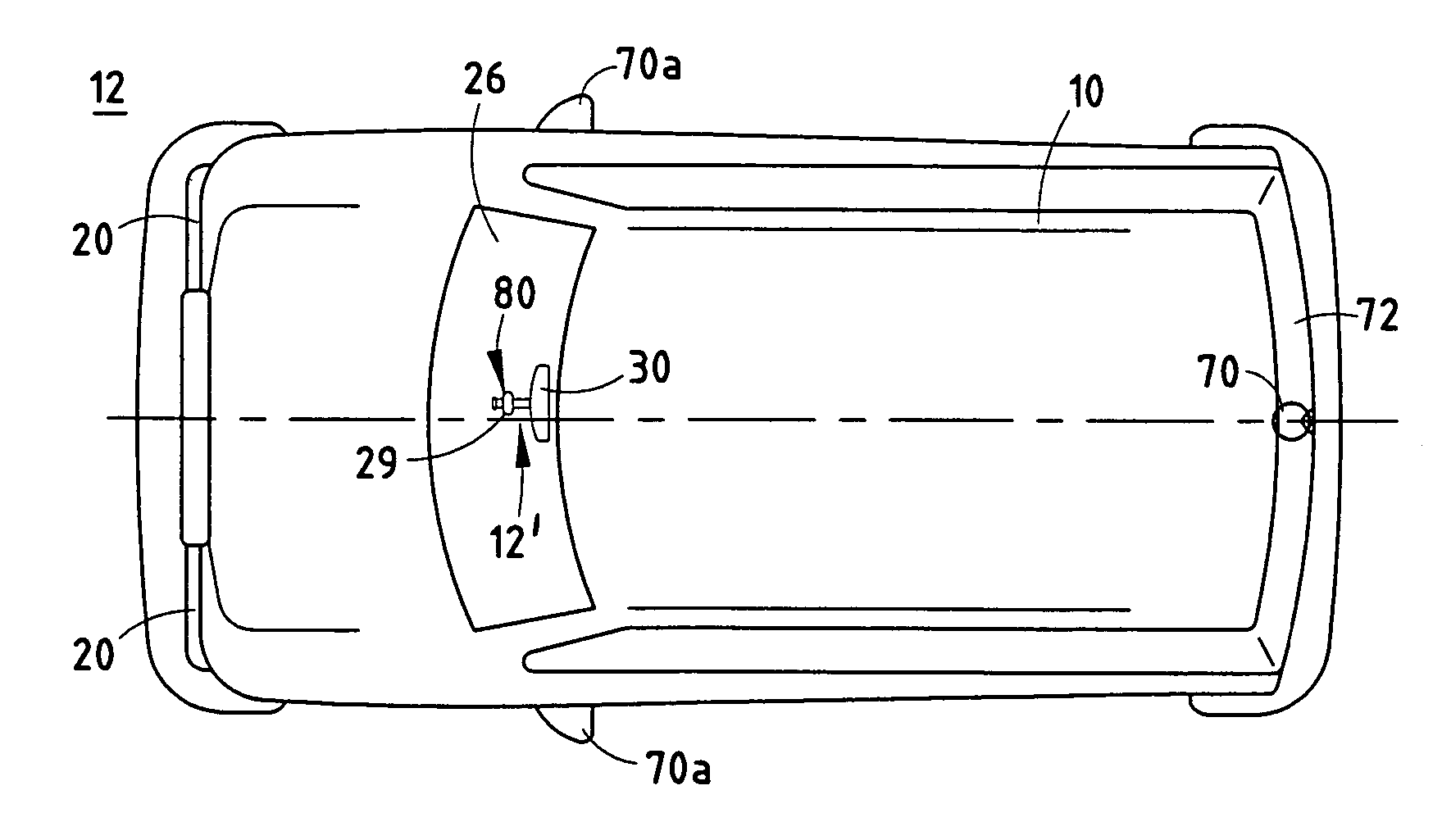
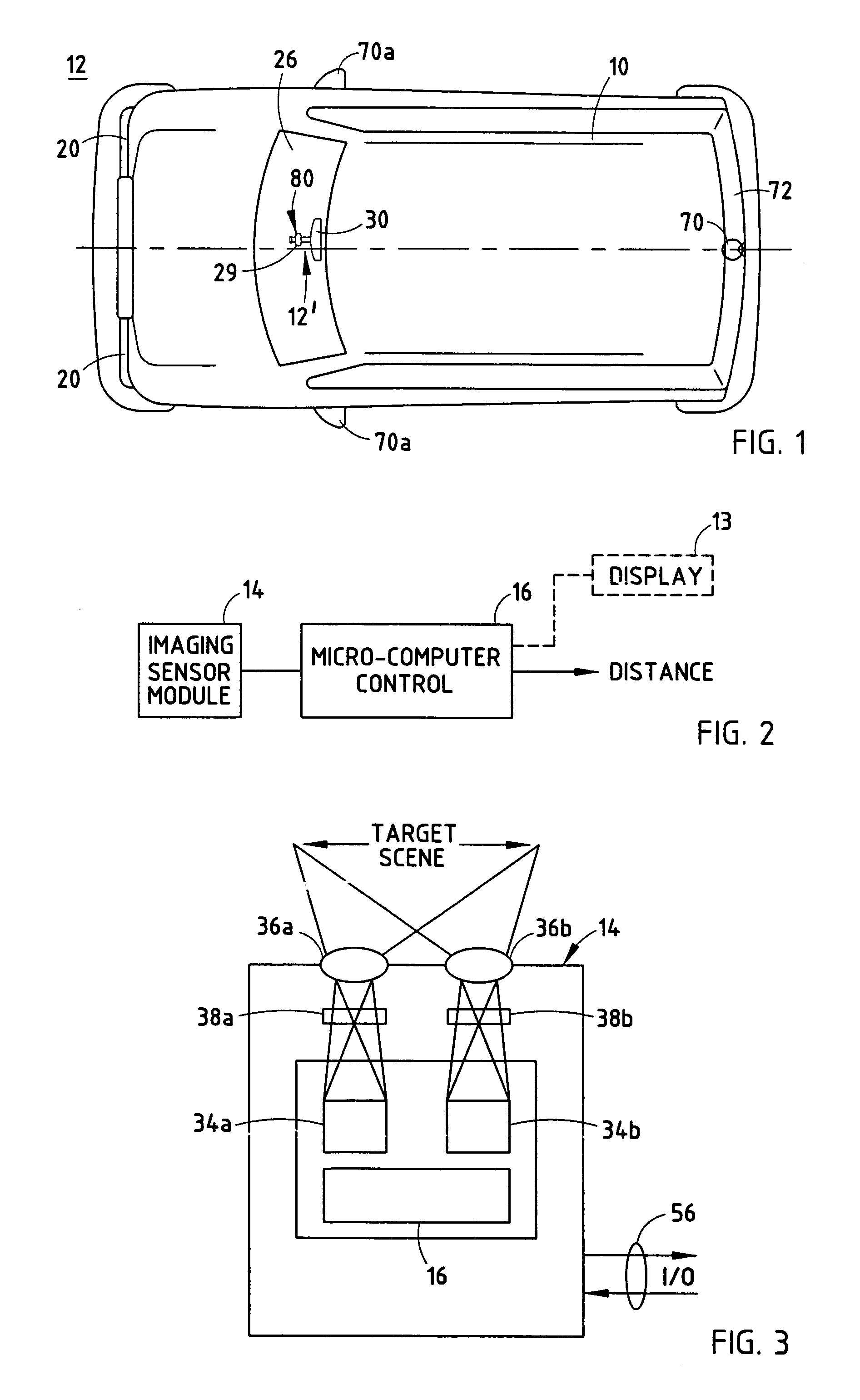
[0032]Referring now specifically to the drawings and the illustrative embodiments depicted therein, a vehicle 10 includes a vehicle imaging system 12 which includes an imaging sensor module 14 and an imaging control 16, as shown in FIGS. 1, 2 and 3. Vehicle imaging system 12 may be a rearview vision system of the type disclosed in commonly assigned U.S. Pat. No. 5,670,935, a rearview vision system of the type disclosed in commonly assigned published PCT Application, International Publication No. WO96 / 38319, published Dec. 5, 1996, a wide angle image capture system of the type disclosed in commonly assigned co-pending U.S. patent application Ser. No. 09 / 199,907, filed Nov. 25, 1998 by Brent J. Bos, et al., now U.S. Pat. No. 6,717,610, a rain sensor and the like of the type disclosed in commonly assigned published PCT application, International Publication No. WO 99 / 23828, published May 14, 1999, or a headlamp dimming control of the type disclosed in U.S. Pat. No. 5,796,094, issued to...


PUM


Abstract

A vehicle imaging system includes an imaging array sensor having a field of view directed outwardly from the vehicle and toward an external scene, first and second optic elements, and a control responsive to an output of the imaging array sensor. The imaging array sensor has at least first and second portions, with the first optic element positioned along a first optic path between the first portion of the imaging array sensor and the external scene, and the second optic element positioned along a second optic path between the second portion of the imaging array sensor and the external scene. The control processes the output and distinguishes the first image and the second image in order to identify objects of interest in the external scene. The control generates a control output in response to the processing.

Description

[0001]The present application is a continuation of U.S. patent application Ser. No. 10 / 047,901, filed Jan. 14, 2002 for VEHICLE IMAGING SYSTEM WITH ACCESSORY CONTROL, now U.S. Pat. No. 6,822,563, which is a continuation of U.S. patent application Ser. No. 09 / 372,915, filed Aug. 12, 1999 for VEHICLE IMAGING SYSTEM WITH STEREO IMAGING, now U.S. Pat. No. 6,396,397, which is a continuation-in-part of U.S. patent application Ser. No. 09 / 313,139, filed on May 17, 1999, now U.S. Pat. No. 6,222,447, which is a continuation of U.S. patent application Ser. No. 08 / 935,336, filed on Sept. 22, 1997, now U.S. Pat. No. 5,949,331, the disclosures of which are hereby incorporated herein by reference; and the present application is a continuation-in-part of U.S. patent application Ser. No. 11 / 545,039, filed Oct. 6, 2006 by Schofield et al. for VEHICLE HEADLIGHT CONTROL USING IMAGING SENSOR, which is a continuation of U.S. patent application Ser. No. 09 / 441,341, filed Nov. 16, 1999 by Schofield et al....

Claims


Application Information

Patent Timeline
Patent Type & Authority Patents(United States)
IPC IPC(8): B60Q1/00B60Q1/02B60Q1/14B60Q11/00B60N2/00B60Q1/52B60R1/00H04N13/239
CPCB60N2/002H04N7/183B60Q9/008B60R1/00B60R1/12G01B11/026G06T7/0022H04N13/0239G06T7/0075B60R11/04G06K9/00825H04N5/335B60Q1/143B60Q2300/41B60Q2300/42B60R2011/0003B60R2011/0026B60R2300/105B60R2300/107B60R2300/30B60R2300/305B60R2300/804B60R2300/8066H04N2013/0081G06T2207/10021G06T2207/10024G06T2207/30252G06T7/97G06T7/593H04N13/239G06V20/584H04N25/00
Inventor BOS, BRENT JSCHOFIELD, KENNETH
Owner MAGNA ELECTRONICS
Why Eureka
Try Eureka