Eureka AIR delivers breakthrough ideas for toughest innovation challenges, trusted by R&D personnel around the world.

Method of driving display panel, luminance correction device for display panel, and driving device for display panel

a technology of luminance correction and display panel, which is applied in the direction of instruments, static indicating devices, etc., can solve the problems of extremely challenging high-speed operation of signal drivers, and the unit of an lsb, so as to eliminate the interruption of video display during use, high gray scale resolution, and high quality

Inactive Publication Date: 2007-06-05
PANASONIC CORP
View PDF20 Cites 224 Cited by
  • Summary
  • Abstract
  • Description
  • Claims
  • Application Information

AI Technical Summary

Benefits of technology

"The present invention provides a driving method for a display panel that overcomes non-uniformity in illumination over time. The method includes changing the luminance setting reference value and capturing luminance information from pixels at predetermined intervals. The luminance correction is carried out by calculating correction values and updating the correction memory. The invention also takes into account the characteristics of the display elements and the degradation of phosphors. The invention allows for optimum correction intervals based on the characteristics of the display elements and the luminance degradation. The luminance correction operations may be carried out during periods other than video output periods, and the intervals between the luminance correction operations may be varied. The invention also allows for highly accurate luminance correction by measuring the degradation characteristics of the display elements and using them in calculating the correction values. The invention further includes an initial stage of illuminating all pixels in the panel one at a time and capturing luminance information from them."

Problems solved by technology

Among the conventional examples described above, PWM is disadvantageous in that the LSB, the smallest unit, is reduced as the number of gray scale levels increases, making what is high-speed operation for a signal driver necessary.
For example, in the case of 8-bit 256-level gray scale that is necessary for a nature video on a 640×480 computer display panel, supposing video is displayed at 60 frames / second, an LSB width of 0.12 μs results, thereby necessitating what is extremely challenging high speed operation for a signal driver.
Furthermore, the capacitance component that is caused by the wiring, increases, and even if the signal driver does carry out high speed operation, current is lost to parallel capacitance, whereby the phenomenon arises such that light is no longer emitted by the unit of an LSB and precision in gray scale expression is adversely affected.
The other method, the system of output amplitude modulation, is not problematic in terms of high speed operation, but when there are numerous gray scale levels, deviations in the outputs of the signal driver become a problem.
For example, in the case of a signal driver having a 100% output of 5 V, the LSB output is 20 mV during 8-bit 256-level gray scale, and it is difficult in terms of both cost and production to ensure this level of accuracy uniformly across all the lines.
This is because it is extremely difficult to make the configuration and process of all the electron-emitting elements exactly the same and because the electron-emitting surfaces are not uniform.
As a result, even if the same driving voltage is applied to each of the elements, varying amounts of current are emitted, resulting in the problem of non-uniformity in luminance.
Furthermore, in the case of displaying the same information over a long period (for example, a total illumination time of 3000 hours), the degradation of the elements progresses more in the elements that have been emitting light than in the elements that have not been emitting light.
Thus, differences in luminance arise, resulting in the problem of the appearance of the given information that had been displayed in the form of a phenomenon similar to sticking.
In this configuration, in accordance with the characteristics of the electron-emitting elements, a log amplifier is connected to the output of a PAM circuit, but if a log amplifier is not also connected to the output of a pulse width controller, a problem arises where the log amplifier does not match with the characteristics.
In addition, while the characteristics of the electron-emitting elements are taken to be the log characteristics, the actual characteristics of the elements do not precisely align with the straight line defining the log characteristics, and thus variation results.
For these reasons, with only a simple log amplifier, it is difficult to output gray scale with accuracy.
The configuration of this prior art example is also problematic in that it cannot counter variation in luminance and change over time in the creation of images.
Because this correction is carried out sequentially on all of the pixels, a certain amount of time is required and the problem of having to interrupt video display during the correction operation arises.
In order to carry out the correction, it is necessary to interrupt video display during use, and this time cannot be ignored or permitted.
Ideally, a display device that does not require correction operation is desired, because having to perform correction operations is not good for workability from the perspective of the user of the image display device and because it contributes to lower quality display.
However, problems sometimes arise in display at low luminance levels.
For this reason, even if the number of divisions of pulse width is reduced and constrain on response speed alleviated, because the amplitude value (applied voltage) is small, the problem arises where response speed slows down to an even greater degree.

Method used


Image

  • Method of driving display panel, luminance correction device for display panel, and driving device for display panel
  • Method of driving display panel, luminance correction device for display panel, and driving device for display panel
  • Method of driving display panel, luminance correction device for display panel, and driving device for display panel

Examples


embodiment 1

Basic Driving Operation of the Present Invention

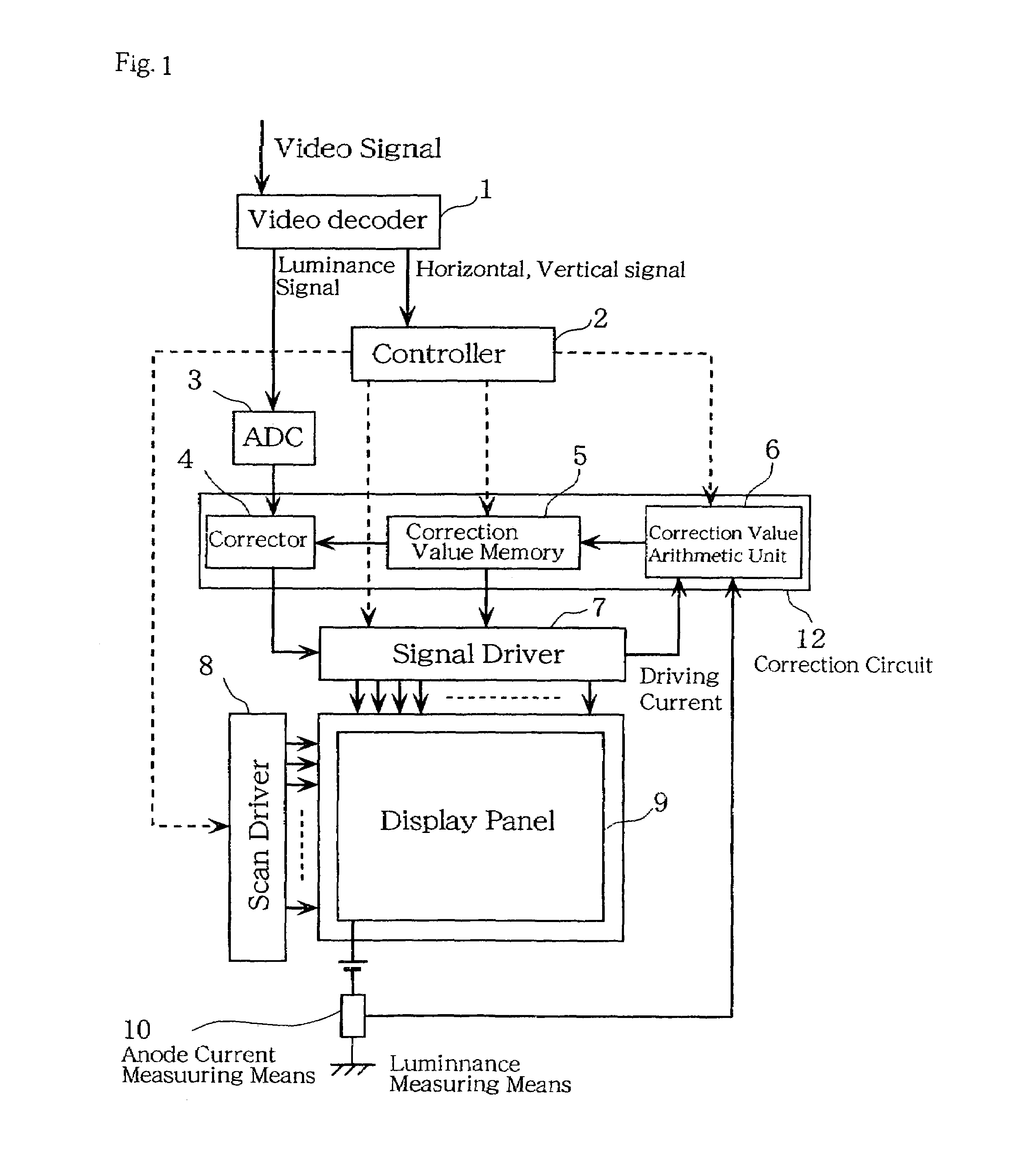
[0112]The operational principle of the present invention is shown in FIG. 1 and is described with reference to the figure.

[0113]Reference numeral 9 denotes a display panel in which numerous, for example, electron-emitting elements are arranged in rows and columns. Display panel electrodes for data input and display panel electrodes for scan signal input are each connected to a driver. Reference numeral 8 denotes a scan driver that sequentially scans, one row at a time, the panel wired in rows and columns. For example, in the scan driver, there is a switching circuit for each row, and the scan driver has a function such that in accordance with the timing of the scanning, only a given selected row is connected to either a direct current voltage source Vy (not shown in figure) or 0 V, while other rows are connected to the other voltage value. Reference numeral 7 denotes a signal driver that applies modulated signals to control the emittin...

embodiment 2

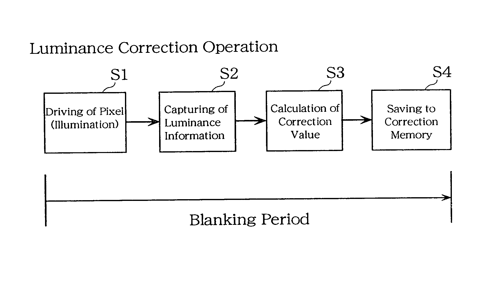
[0212]Embodiment 2 describes another example of an operation for correction of change over time. A method of correcting luminance in accordance with the present embodiment 2 will be described with reference to FIG. 28. Consider a given blanking period (horizontal or vertical). A pixel is driven to illuminate, luminance information (for example, anode current) is captured, a correction value for driving is calculated, and this correction value is stored in the correction memory. This series of operations is carried out during a blanking period. Carrying out this operation during a blanking period makes luminance correction operation that does not affect video output possible. In addition, because the pixels are illuminated one at a time and for extremely short durations, this method is advantageous in that the user cannot perceive the emitting of light.

[0213]For example, suppose that this operation is carried out during an NTSC horizontal blanking period. If the element is capable of...

embodiment 3

[0217]Embodiment 3 describes another example of an operation for correction of change over time. A method of correcting luminance of the present embodiment 3 is shown in FIG. 29. Consider a given blanking period (horizontal or vertical). During this blanking period, operations of driving a pixel to illuminate and capturing luminance information (for example, anode current) only are carried out. This method, intended for cases of increased resolution and shortened blanking periods or the like, is such that only the minimum number of operations is carried out during a blanking period. As long as luminance information is captured during the blanking period, it is not a problem that the subsequent operations of correction calculation and memory storage overlap with the video signal operation or be carried out in parallel with the video signal operation.

[0218]In addition, it is possible to prepare a luminance information temporary storage memory (not shown in figure), to first carry out ...


PUM


Abstract

In conventional methods of correction luminance in displays, it has been necessary to interrupt video display during use in order to carry out correction. This is a problem in that interruptions are not good for workability from the perspective of the user of the image display device. In consideration of this, the present invention realizes a display without non-uniformity in illumination with respect to both initial characteristics and change over time by measuring anode current of an FED and creating a luminance correction memory. In addition, by illuminating arbitrary pixels during video idle periods, capturing the luminance information from the pixels, and renewing a correction memory based on this luminance information, correction for change over time is possible without interrupting video display. Thus, a display device that can maintain high quality images is provided.

Description

TECHNICAL FIELD[0001]The present invention relates to light-emitting elements such as electron-emitting elements and organic EL elements, as well as to display elements that are made up of a plurality of these light-emitting elements. In particular, the present invention relates to a method of driving where luminance variation that arises as a result of change over time is corrected, to a luminance correction device thereof, and to a driving device that utilizes thereof.BACKGROUND ARTFirst Background Art[0002]The configuration of a display device that utilizes conventional electron-emitting elements is shown in FIG. 46. In FIG. 46, reference numeral 509 denotes a matrix display panel with a plurality of signal lines and a plurality of scan lines, reference numeral 507 denotes a signal driver for driving the signal lines, reference numeral 508 denotes a scan driver for driving the scan lines, and reference numeral 502 denotes a controller for controlling the signal driver 507 and the...

Claims


Application Information

Patent Timeline
Patent Type & Authority Patents(United States)
IPC IPC(8): G09G3/30G09G3/20G09G3/22G09G3/32
CPCG09G3/2081G09G3/22G09G3/3216G09G2320/048G09G2360/145G09G3/2011G09G3/2014G09G3/2018G09G3/2077G09G3/3208G09G2300/06G09G2320/0252G09G2320/0276G09G2320/0285G09G2320/029G09G2320/0295G09G2320/043G09G3/30
Inventor KAWASE, TORUKUROKAWA, HIDEOAKIYAMA, KOJISHIRATORI, TETSUYA
Owner PANASONIC CORP
Why Eureka
Eureka Blog
Learn More