
Serial media independent interface

a serial media and interface technology, applied in the field of network computing, can solve the problems of error, mac and phy interface expense, and obvious impracticality, and achieve the effect of avoiding error, reducing the cost of mac and phy interface, and reducing the cost of phy interfa

Inactive Publication Date: 2007-06-05
CISCO TECH INC
View PDF28 Cites 14 Cited by
  • Summary
  • Abstract
  • Description
  • Claims
  • Application Information

AI Technical Summary

Problems solved by technology

Obviously this is impractical.
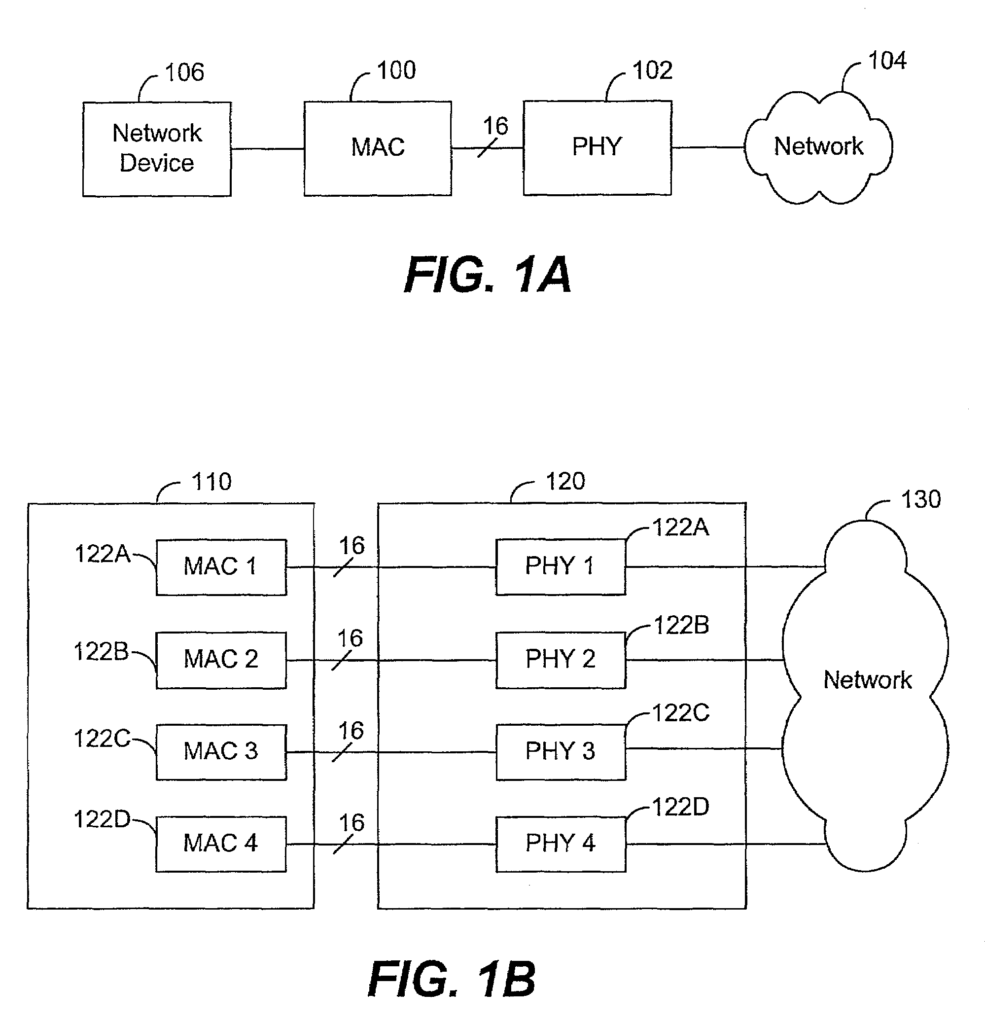
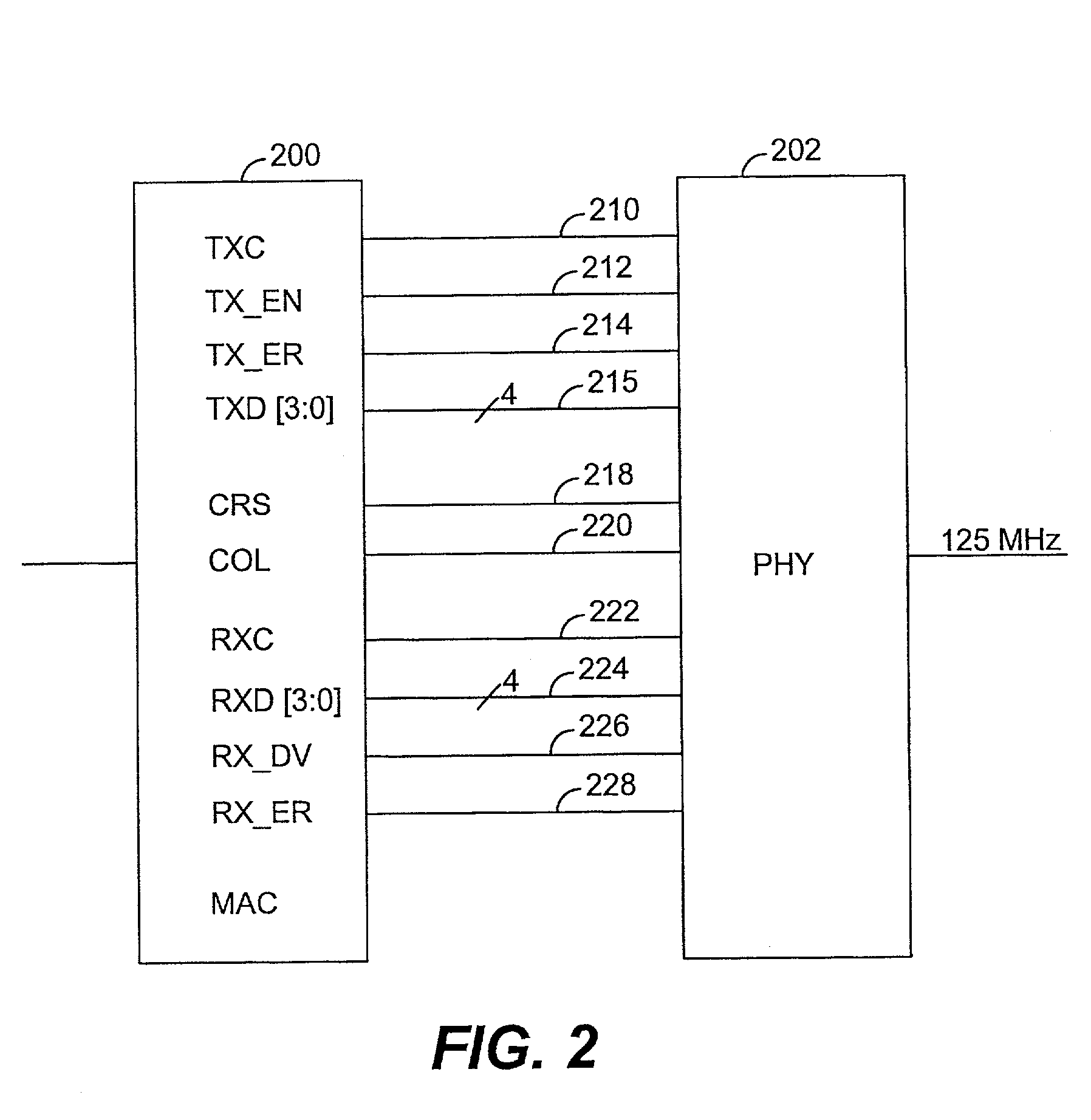
Thus, the requirement of 16 pins for data and control in the standard MII specification adds to the expense of MAC and PHY interfaces both by increasing the number of pins required on chips and by reducing the number of MACs and PHYs which may be combined on a single chip.
There is a finite probability that good data may match the specific data pattern causing the MACs to determine that an error has occurred when, in fact, no error has occurred.
However, the RMII is designed so that the probability of such mistakes occurring is acceptably small to the system designers.

Method used


Image

  • Serial media independent interface
  • Serial media independent interface
  • Serial media independent interface

Examples


Embodiment Construction

[0035]Reference will now be made in detail to a preferred embodiment of the invention. An example of the preferred embodiment is illustrated in the accompanying drawings. While the invention will be described in conjunction with that preferred embodiment, it will be understood that it is not intended to limit the invention to one preferred embodiment. On the contrary, it is intended to cover alternatives, modifications, and equivalents as may be included within the spirit and scope of the invention as defined by the appended claims. In the following description, numerous specific details are set forth in order to provide a thorough understanding of the present invention. The present invention may be practiced without some or all of these specific details. In other instances, well known process operations have not been described in detail in order not to unnecessarily obscure the present invention.

[0036]The present invention provides a 10 / 100Base-T MAC to PHY interface requiring only...


PUM


Abstract

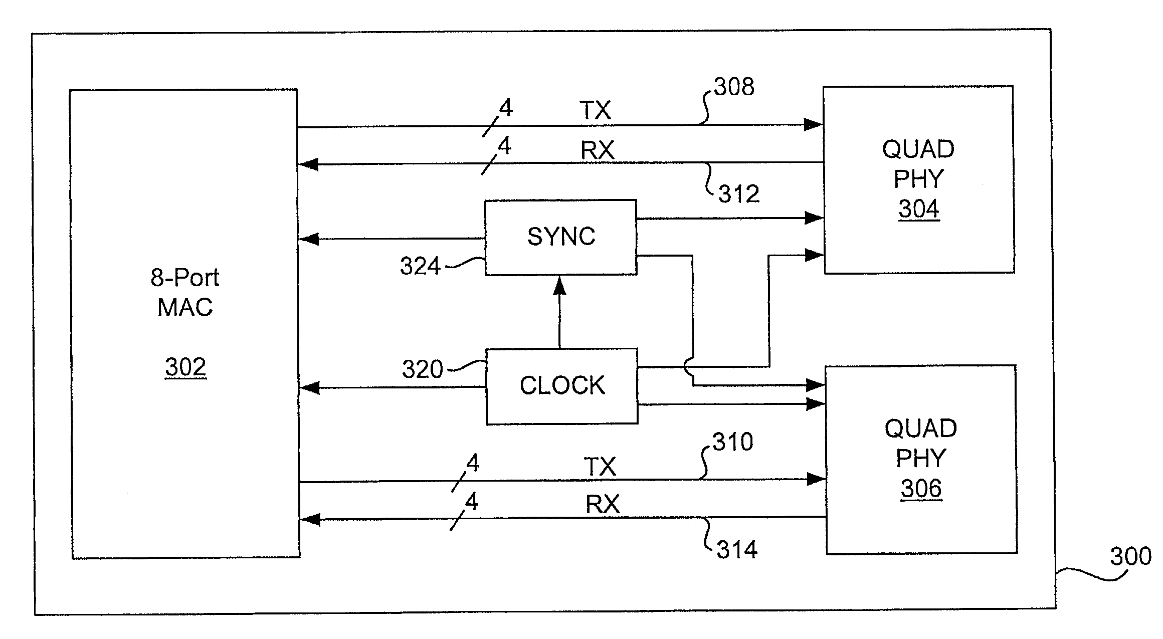
Provided is a 10 / 100Base-T MAC to PHY interface requiring only two wires (pins) per port, with two additional global wires: a clock wire (pin), and a synchronization wire (pin). This reduction in the number of pins associated with each port is achieved by time-division multiplexing wherein each time-division multiplexed wire combines a plurality of definitions from the conventional 100Base-T interface specified by IEEE 802.3u (clause 22). As a result, each port has its own pair of associated time-division multiplexed wires (pins) and the addition of each port simply requires two additional wires. According to a preferred embodiment of the present invention, information normally transferred on sixteen wires in a conventional 100Base-T interface at 25 MHz is time-division multiplexed onto two wires (corresponding to two pins) that transfer data at 125 MHz, five times the speed of conventional interfaces. Importantly, this multiplexing is done on a port by port basis. Therefore, the number of pins required for a MAC to transceiver interface is two times the number of ports plus two instead of sixteen times the number of ports, and the addition of each additional port requires only two more wires (pins).

Description

CROSS-REFERENCE TO RELATED APPLICATIONS[0001]This is a Continuation application of co-pending prior application Ser. No. 09 / 088,956 filed on Jun. 2, 1998.[0002]This application is related to co-pending U.S. patent application Ser. Nos. 09 / 089,033 and 09 / 089,312 filed concurrently herewith, which are incorporated herein by reference for all purposes.BACKGROUND OF THE INVENTION[0003]The present invention relates generally to network computing. More specifically, the present invention relates to methods and apparatuses for connecting a system chip to a 10 / 100Base-T transceiver, and in particular, to a reduced pin-count serial media independent interface.[0004]In computer network systems there is typically a natural division between chips handling the physical layer, which is responsible for transmitting data on the network, and the system chips, which perform logical operations with data transmitted on the network. Ethernet hubs, routers and switches are composed of multiple ports, and...

Claims


Application Information

Patent Timeline
Patent Type & Authority Patents(United States)
IPC IPC(8): H04L12/28H04L12/413H04L12/56
CPCH04L7/0008H04L12/40006H04L12/413H04J3/0685
Inventor FINDLATER, STEWARTBECHTOLSHEIM, ANDREAS V.
Owner CISCO TECH INC
Learn More