Integrated optic polarization converter based on structural chirality

a technology of optical polarization converter and structural chirality, applied in the field of integrated optic polarization converter, can solve the problems of polarization dependent performance, cumbersome implementation of bulk optics, and difficult if not impossible to compensate both simultaneously

Inactive Publication Date: 2007-06-05
GOOGLE LLC +1
View PDF5 Cites 28 Cited by
  • Summary
  • Abstract
  • Description
  • Claims
  • Application Information

AI Technical Summary

Problems solved by technology

Since most integrated optic components are sensitive to both propagation velocity and guide-to-guide coupling, these effects result in polarization dependent performance, a result that is not compatible with the random polarization state emanating from the standard single mode fiber used in telecom applications.
However, while one or the other of these effects may be compensated in this manner for a particular device, as the index contrast increases it becomes difficult if not impossible to compensate both simultaneously in a manner that applies to all devices on the chip.
While such an approach, commonly referred to as a “polarization diversity” scheme, is feasible, when implemented with bulk optics it is also cumbersome.
Aligning PM fibers is difficult and expensive.
However, most of the devices proposed to date rely on the coupling of a pair of waveguide modes.
Further, such approaches are very sensitive to fabrication errors.
It has been proposed and demonstrated that a polarization splitter based on mode evolution can be formed, however, this approach has the disadvantage of requiring multiple waveguide materials.

Method used


Image

  • Integrated optic polarization converter based on structural chirality
  • Integrated optic polarization converter based on structural chirality
  • Integrated optic polarization converter based on structural chirality

Examples


Embodiment Construction

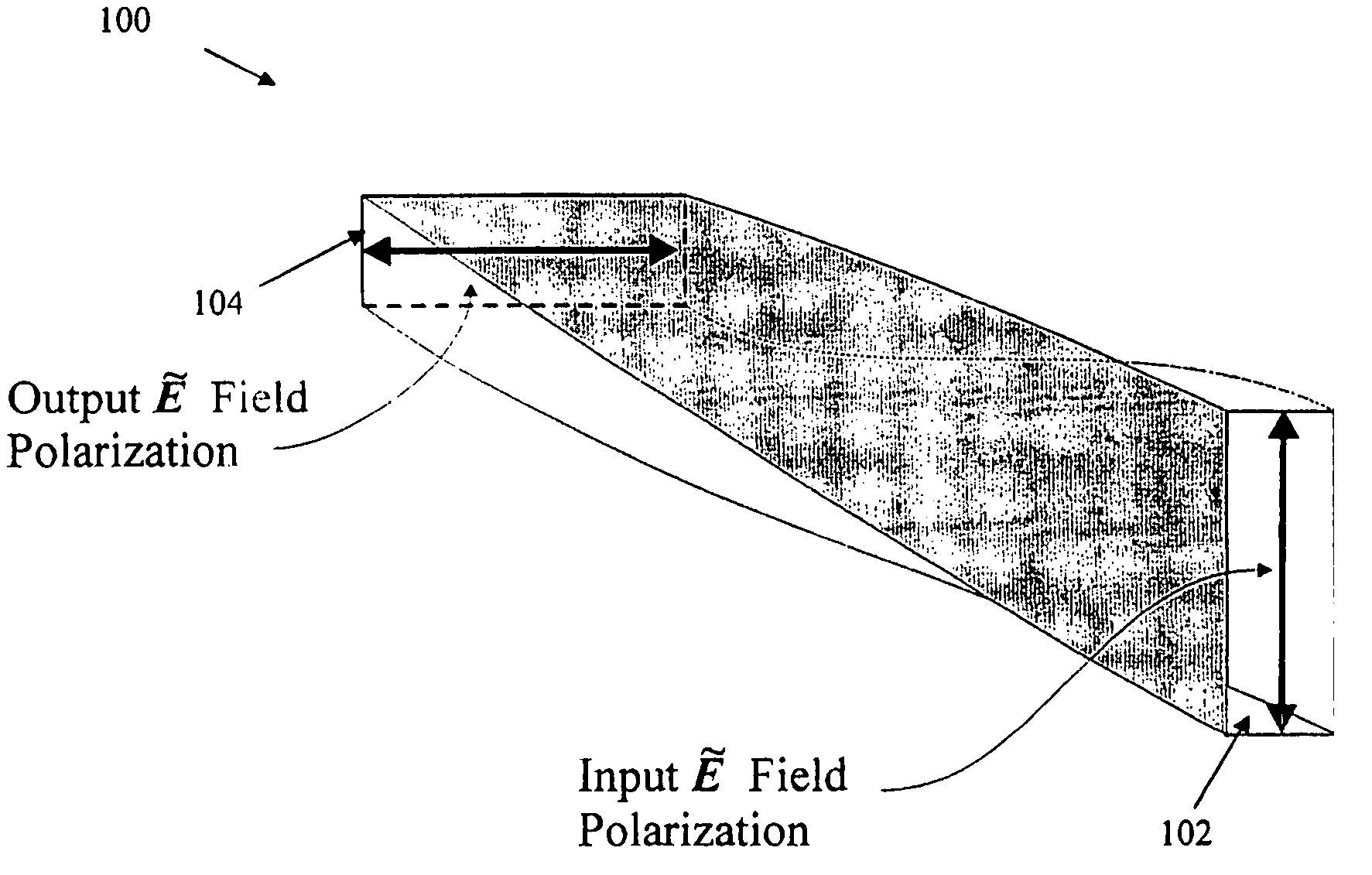
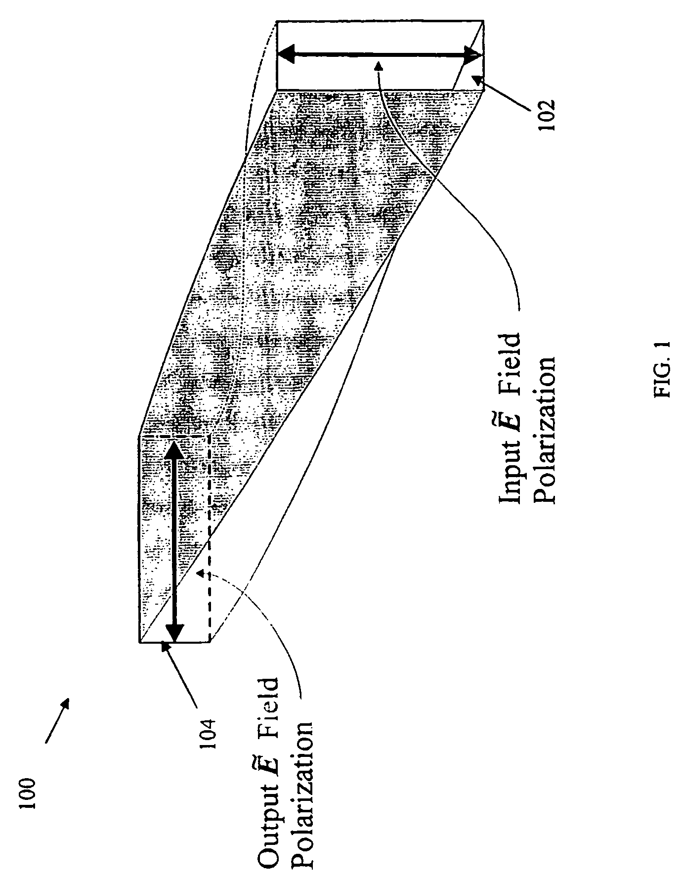
[0027]The mode structure for a general rectangular dielectric waveguide consists of a minimum of two guided electromagnetic modes, a TE (or quasi-TE) mode and a TM (or quasi-TM) mode, and an infinite sum of unguided (or radiation) electromagnetic modes. If a rectangular waveguide is rotated by 90°, its mode structure is similarly rotated with the TE mode becoming the TM mode and vice-versa. Therefore, a smooth transition between a rectangular waveguide and its rotated counterpart should enable polarization conversion through mode evolution. However, any perturbation to the initial structure will induce coupling between the modes. For a mode evolution approach to work, power exchange between the modes must be inhibited.

[0028]A way to transition between a rectangular waveguide and its rotated counterpart is to twist the initial structure. FIG. 1 is a schematic diagram of an adiabatically twisted dielectric waveguide 100 having an input 102 and output 104. The twisting of the waveguide...


PUM

PropertyMeasurementUnit
lengthaaaaaaaaaa
lengthaaaaaaaaaa
lengthsaaaaaaaaaa

Abstract

An integrated optic polarization converter includes a plurality of core layers used to approximate a gradually twisted waveguide and therein adiabatically transform a propagating mode from an initial polarization state to a different final polarization state.

Description

PRIORITY INFORMATION[0001]This application is the U.S. national stage application of International (PCT) Patent Application Ser. No. PCT / US2003 / 034577, filed Oct. 30, 2003, which claims priority from provisional application Ser. Nos. 60 / 422,414, filed Oct. 30, 2002, and 60 / 478,751, filed Jun. 16, 2003. The disclosures of these three applications are incorporated herein by reference in their entirety.BACKGROUND OF THE INVENTION[0002]The invention relates to the field of integrated optic polarization converters, and in particular to integrated optic polarization converters based on mode evolution or structural chirality.[0003]As the prevalence of fiber optic communication grows, the demand for more intricate processing of optical signals continues to increase. Since integrated optic devices allow for integration of many optical functions on a chip, integrated optic approaches will likely fill the demand for more intricate optical signal processing. However, in order to improve the fun...

Claims


Application Information

Patent Timeline
Patent Type & Authority Patents(United States)
IPC IPC(8): G02B6/28G02B6/126G02B6/14G02F1/01
CPCG02B6/126G02B6/14G02B6/2726G02B6/2766
Inventor WATTS, MICHAEL R.HAUS, LEGAL REPRESENTATIVE, ELEANOR L.CHERCHI, MATTEOHAUS, DECEASED, HERMANN A.
Owner GOOGLE LLC
Why Eureka
Try Eureka