Controlling airflow in an air conditioning system for control of system discharge temperature and humidity

a technology of airflow control and air conditioning system, which is applied in the direction of domestic cooling equipment, heating types, instruments, etc., can solve the problems of poor system efficiency, discomfort for occupants of space, and occupants of space will experience relatively cold air circulation and discomfort, so as to improve system operating efficiency and reduce discomfort

Active Publication Date: 2007-06-12
TRANE INT INC
View PDF10 Cites 53 Cited by
  • Summary
  • Abstract
  • Description
  • Claims
  • Application Information

AI Technical Summary

Benefits of technology

[0003]The present invention provides systems and methods to control airflow rates in air conditioning systems to improve system operating efficiency, reduce discomfort from cold airflow into a controlled space on system startup, for example, control humidity in a space served by an air conditioning system and control discharge air temperature of a heating and / or cooling system.

Problems solved by technology

In forced airflow air conditioning systems, a longstanding problem has been one of attempting to set the proper airflow rate for an air handler, furnace or heat pump or a combination thereof to match system capacity at the time of installation.
This is a difficult and nettlesome problem to overcome and often the proper airflow is not set thereby causing poor system efficiency and discomfort to occupants of the space being served by the system.
Thus, the occupants of the space will experience relatively cold air circulation and discomfort.

Method used


Image

  • Controlling airflow in an air conditioning system for control of system discharge temperature and humidity
  • Controlling airflow in an air conditioning system for control of system discharge temperature and humidity
  • Controlling airflow in an air conditioning system for control of system discharge temperature and humidity

Examples


Embodiment Construction

[0013]In the description which follows like elements are marked throughout the specification and drawing with the same reference numerals, respectively. The drawing figures may be in somewhat schematic form and flow diagrams may show only major steps in accordance with the invention and may otherwise be abbreviated in the interest of clarity and conciseness.

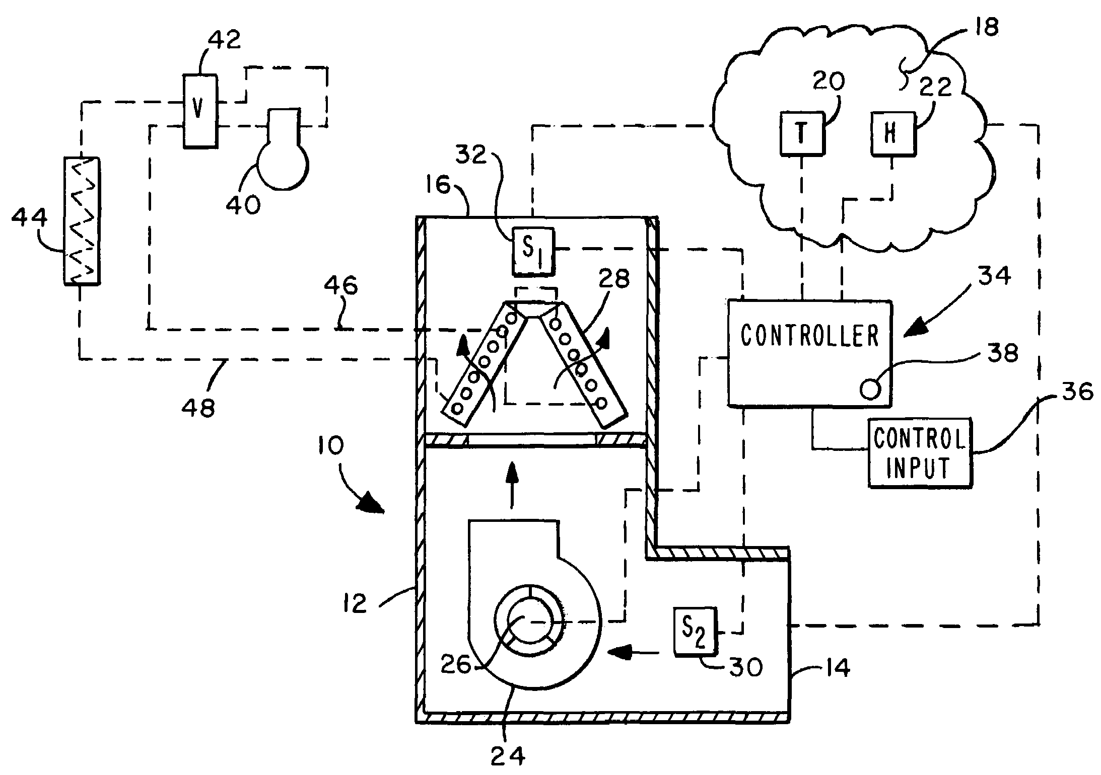
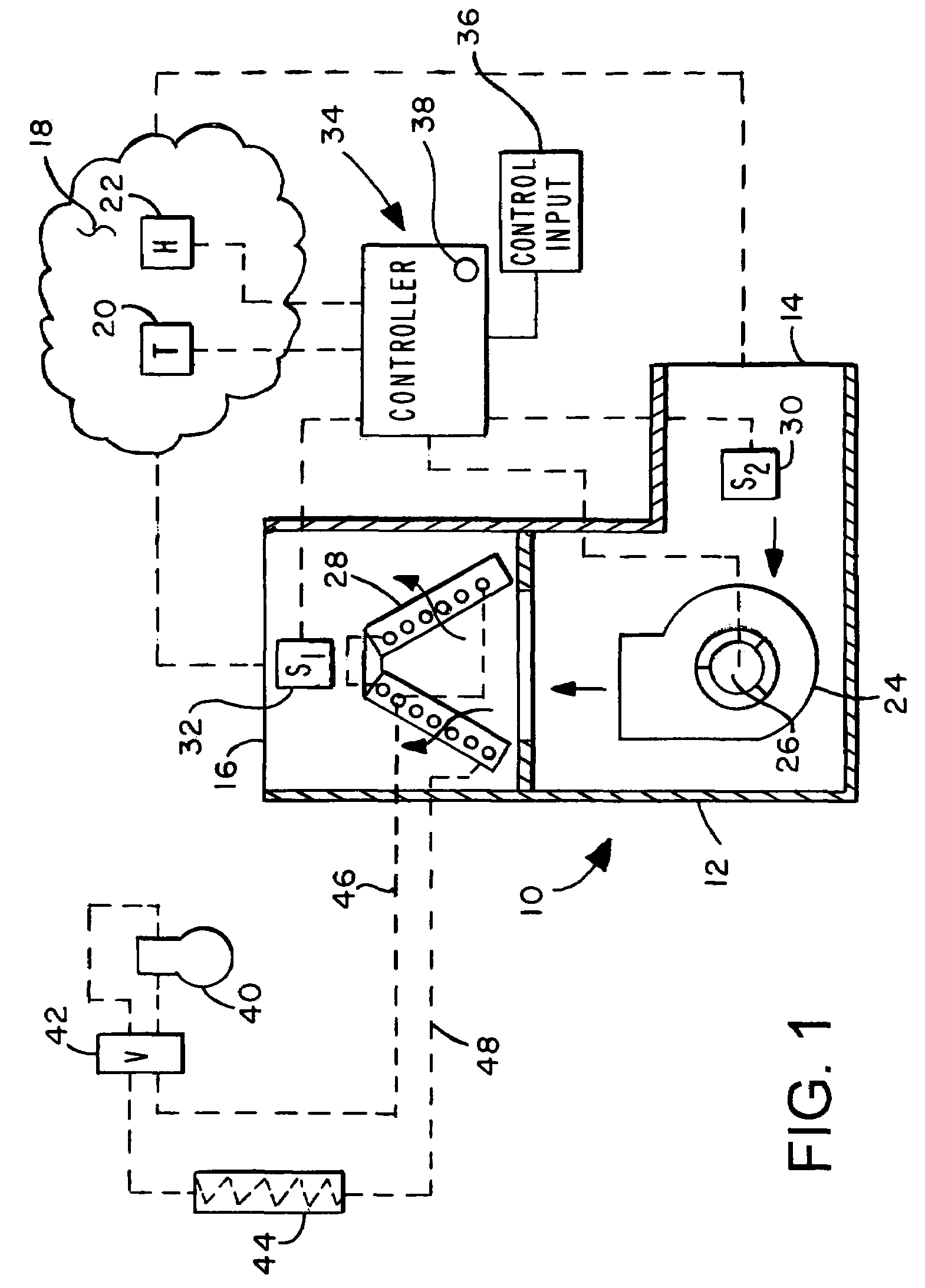
[0014]Referring to FIG. 1, there is illustrated an air conditioning system in accordance with the invention and generally designated by the numeral 10. The system 10 includes a cabinet 12 including an air inlet opening 14 and an air discharge opening 16. The system 10 is adapted to provide conditioned air to a controlled space 18 at which a temperature control sensor or thermostat 20 may be disposed. A second sensor comprising a humidity sensor or humidistat 22 may also be disposed in the controlled space 18, which space is operable to receive air discharged from the system 10 through the discharge opening 16 and to return air ci...


PUM


Abstract

An air conditioning system may comprise an air handler, heat pump or fossil fuel furnace and may include a variable speed blower for conducting air through the system and operably connected to a controller which is also connected to a thermostat and / or humidity sensor. A discharge air temperature sensor may be disposed downstream of or embedded in a heat exchanger of the air conditioning system and connected to the controller for controlling the blower speed and airflow through the system. The amount of heating or cooling effect produced by the heat exchanger or blower speed may be adjusted to provide a constant discharge temperature or lower the humidity of air returning to a controlled space.

Description

BACKGROUND OF THE INVENTION[0001]In forced airflow air conditioning systems, a longstanding problem has been one of attempting to set the proper airflow rate for an air handler, furnace or heat pump or a combination thereof to match system capacity at the time of installation. This is a difficult and nettlesome problem to overcome and often the proper airflow is not set thereby causing poor system efficiency and discomfort to occupants of the space being served by the system.[0002]For example, on startup of air conditioning systems, such as heat pumps, as well as systems which incorporate other types of heating sources, a constant speed circulating blower will deliver relatively cold air to the controlled space before the heat pump heating coil is at a stabilized operating condition and outputting sufficient heat to the controlled space. Thus, the occupants of the space will experience relatively cold air circulation and discomfort. In other situations, such as when operating in the...

Claims


Application Information

Patent Timeline
Patent Type & Authority Patents(United States)
IPC IPC(8): F25B49/00F24F3/14F25D17/04F24F11/00
CPCF24F11/001F24F11/0079F24F11/0012F24F11/0015Y02B30/746F24F11/30F24F2110/00F24F2110/10F24F2110/20F24F11/77Y02B30/70F24F11/76F24F11/62
Inventor HELT, ROBERT W.
Owner TRANE INT INC
Why Eureka
Try Eureka