Ophthalmic laser treatment apparatus

a laser treatment and ophthalmology technology, applied in the field of ophthalmic laser treatment apparatus, can solve the problems of ophthalmology division burden of cost, limited treatment of choroidal neovascularization, and large space needed for installation of those apparatuses

Inactive Publication Date: 2007-06-12
NIDEK CO LTD
View PDF8 Cites 33 Cited by
  • Summary
  • Abstract
  • Description
  • Claims
  • Application Information

AI Technical Summary

Problems solved by technology

This would pose a limit to the treatment for choroidal neovascularization in central fovea or a contiguous region thereto.
However, preparation of the special purpose apparatuses adapted for respective treatments would cause a problem that a wide space is needed for installation of those apparatuses.
In addition, the preparation of the specially designed apparatuses would place a burden in cost on the ophthalmology division or the like.

Method used


Image

  • Ophthalmic laser treatment apparatus
  • Ophthalmic laser treatment apparatus
  • Ophthalmic laser treatment apparatus

Examples


first embodiment

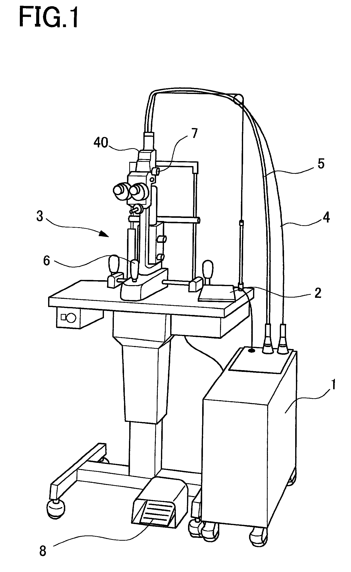
[0021]A detailed description of preferred embodiments of a laser treatment apparatus embodying the present invention will now be given referring to the accompanying drawings. In the embodiments, an apparatus capable of performing both of photocoagulation and PDT is exemplified. FIG. 1 is a schematic perspective view of the laser treatment apparatus in a

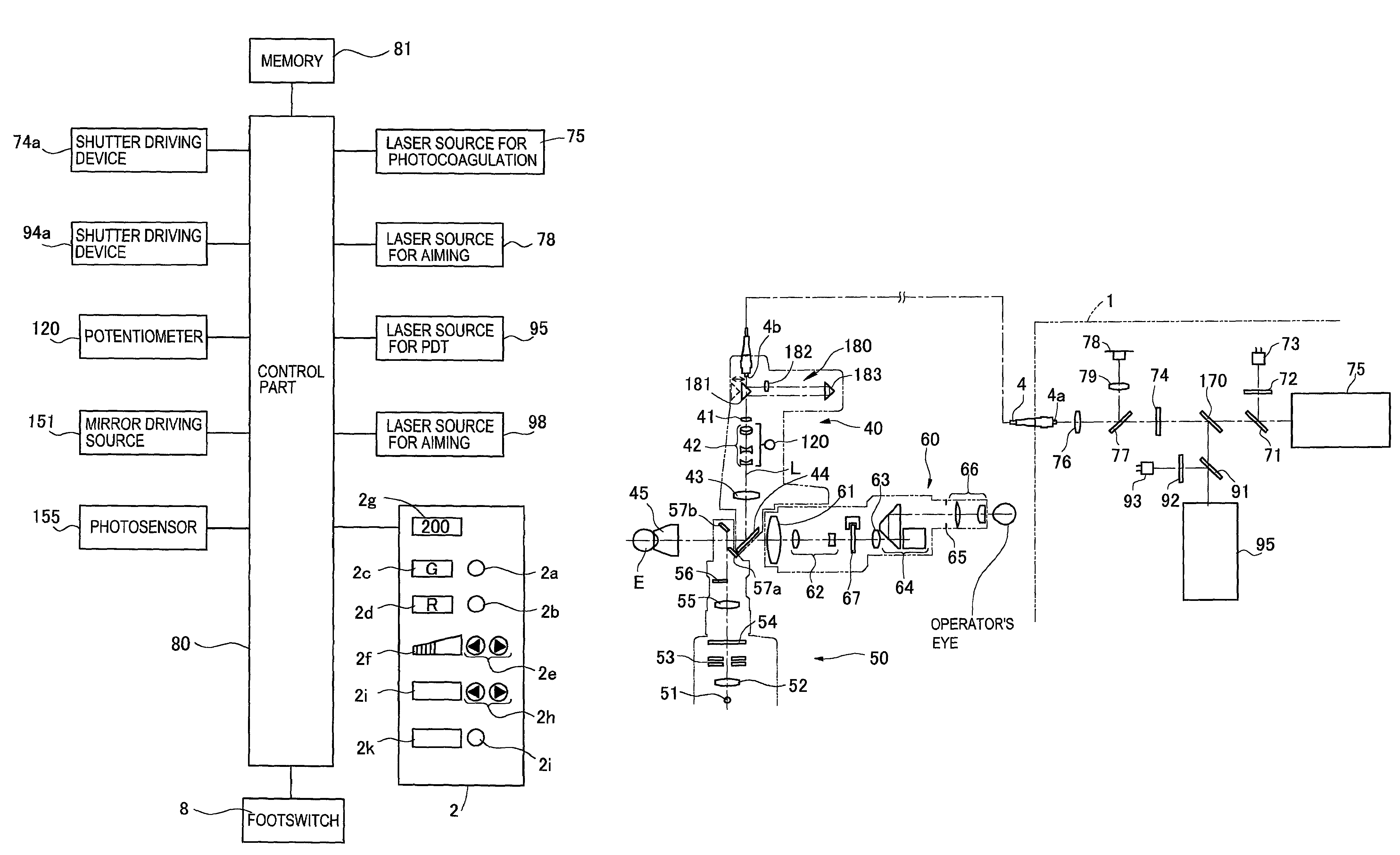
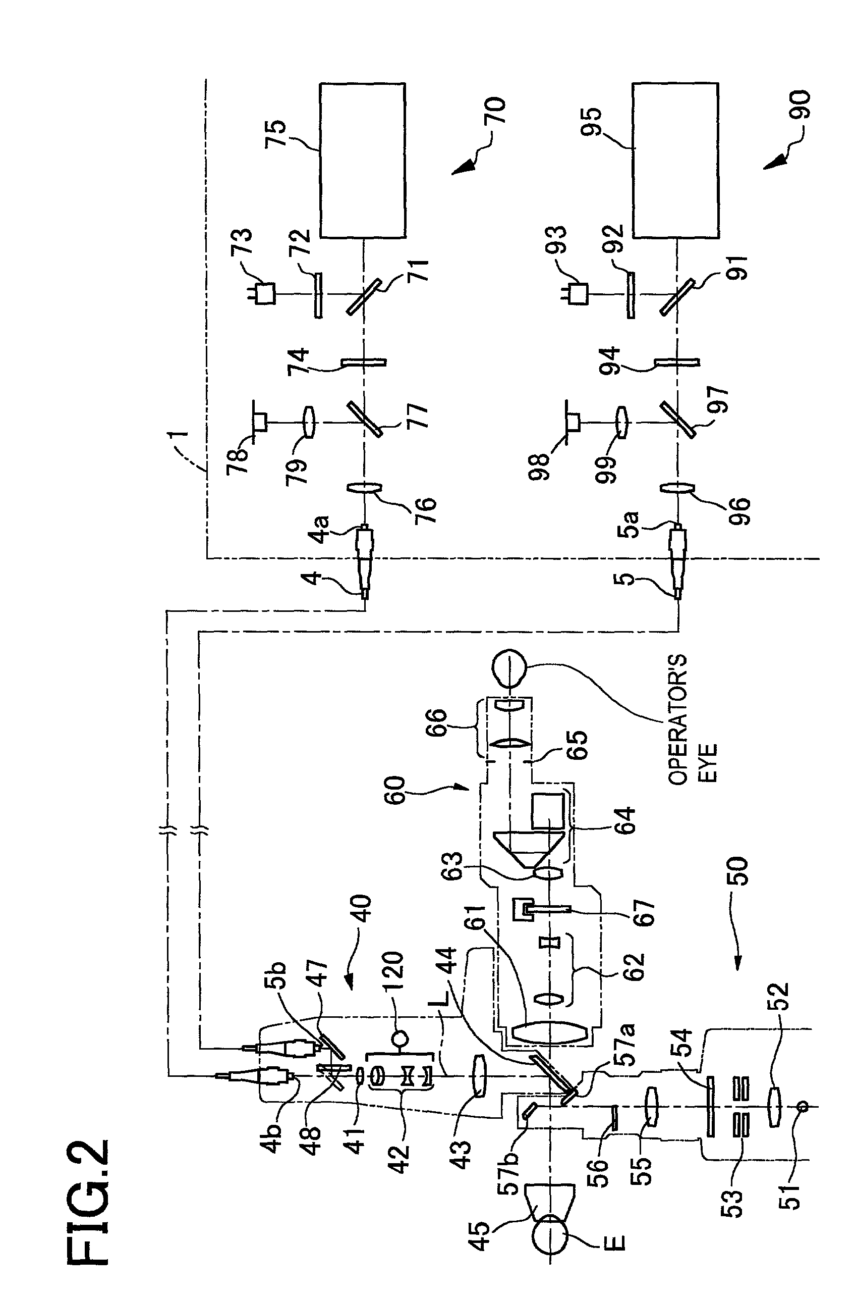
[0022]Numeral 1 is a main unit of the laser treatment apparatus, including a laser source unit 70 for photocoagulation and a laser source unit 90 for PDT, both of which will be mentioned later, and other components. Numeral 2 is a control panel used for inputting and setting irradiation conditions of a treatment laser beam and an aiming laser beam, etc. Numeral 3 is a slit lamp delivery including an illumination optical system and an observation optical system. An irradiation unit 40 provided with an irradiation optical system (a light delivery optical system) for irradiating a treatment laser beam to a patient's eye is attached to th...

second embodiment

[0049]In the second embodiment, similarly, the magnification changing optical system of the irradiation unit 40 can be used in common for both the photocoagulation and the PDT. The same slit lamp delivery unit 3 can be used to selectively, appropriately perform the photocoagulation and the PDT.

[0050]The present invention may be embodied in other specific forms without departing from the spirit or essential characteristics thereof. For instance, the above embodiments exemplify the apparatus adaptable to selectively perform the PDT and the photocoagulation. The apparatus of the invention may be arranged to selectively perform the TTT and the photocoagulation. In this case, the laser source 90 for PDT is replaced with a laser source capable of a treatment laser beam having a wavelength needed for TTT, for example, a laser diode which emits a treatment laser beam with a wavelength of 810 nm. In the case of TTT, a large spot size is used as in the case of PDT. It is usually determined in...


PUM


Abstract

An ophthalmic laser treatment apparatus which irradiates a laser beam to a patient's eye to be treated is disclosed. The apparatus includes: a first optical fiber which delivers a first laser beam emitted from a first laser source; a first light delivery optical system which forms an image of an emission end surface of the first optical fiber on the affected part of the eye in a predetermined first spot size being in a range of 50 μm to 1000 μm; a second optical fiber which delivers a second laser beam emitted from a second laser source; and a second light delivery optical system which forms an image of an emission end surface of the second optical fiber on the affected part of the eye in a predetermined second spot size in a range of 500 μm to 7000 μm.

Description

BACKGROUND OF THE INVENTION[0001]1. Field of the Invention[0002]The present invention relates to an ophthalmic laser treatment apparatus which is used to treat a patient's eye by irradiating the eye with a laser beam.[0003]2. Description of Related Art[0004]Photocoagulation or the like of the tissue of fundus is generally performed as ophthalmic laser treatment. As a recent treatment method for age-related macular degeneration (AMD), attention is being given to Photodynamic Therapy (PDT) and Transpupillary Thermotherapy (TTT).[0005]The PDT is a treatment method to treat choroidal neovascularization by intravenously injecting a photosensitive material (a pharmaceutical drug) having the property of selectively accumulating in atypical tissue such as choroidal neovascularization into a patient's arm, and irradiating an affected part of the fundus with a laser beam with a specific absorption wavelength to the drug, so that the affected part is cured by the active oxygen having cytotoxic...

Claims


Application Information

Patent Timeline
Patent Type & Authority Patents(United States)
IPC IPC(8): A61B18/18A61B18/22A61B18/20A61F9/007A61F9/008A61N5/06
CPCA61F9/008A61F9/00821A61B18/22A61B2018/207A61F2009/00863A61B2018/208A61N5/062
Inventor NAKAMURA, HIROKAZU
Owner NIDEK CO LTD
Why Eureka
Try Eureka