Floating-point type digital signal reversible encoding method, decoding method, apparatuses therefor, and programs therefor

a digital signal and reversible encoding technology, applied in the direction of electrical equipment, code conversion, etc., can solve the problems that entropy compression coding or the like cannot be expected to provide cannot achieve a high compression ratio, so as to achieve efficient compression and increase the scale of processing equipment and program

Active Publication Date: 2007-06-12
NIPPON TELEGRAPH & TELEPHONE CORP
View PDF5 Cites 46 Cited by
  • Summary
  • Abstract
  • Description
  • Claims
  • Application Information

AI Technical Summary

Benefits of technology

[0017]According to the present invention, a digital signal sample sequence in the floating-point format can be efficiently compressed. In addition, a typical compression-coding module designed for a signal sample sequence in the integer format can be used, and both the integer format and the floating-point format can be handled without increasing significantly the scale of the processing apparatus and the program.

Problems solved by technology

Thus, even if the bit arrangement transformation described above is performed, the entropy compression coding or the like cannot be expected to provide a high compression ratio.
Therefore, even if the lossless predictive coding method disclosed in the non-patent literature 1 described above is applied, a higher compression ratio cannot be expected.

Method used


Image

  • Floating-point type digital signal reversible encoding method, decoding method, apparatuses therefor, and programs therefor
  • Floating-point type digital signal reversible encoding method, decoding method, apparatuses therefor, and programs therefor
  • Floating-point type digital signal reversible encoding method, decoding method, apparatuses therefor, and programs therefor

Examples


first embodiment

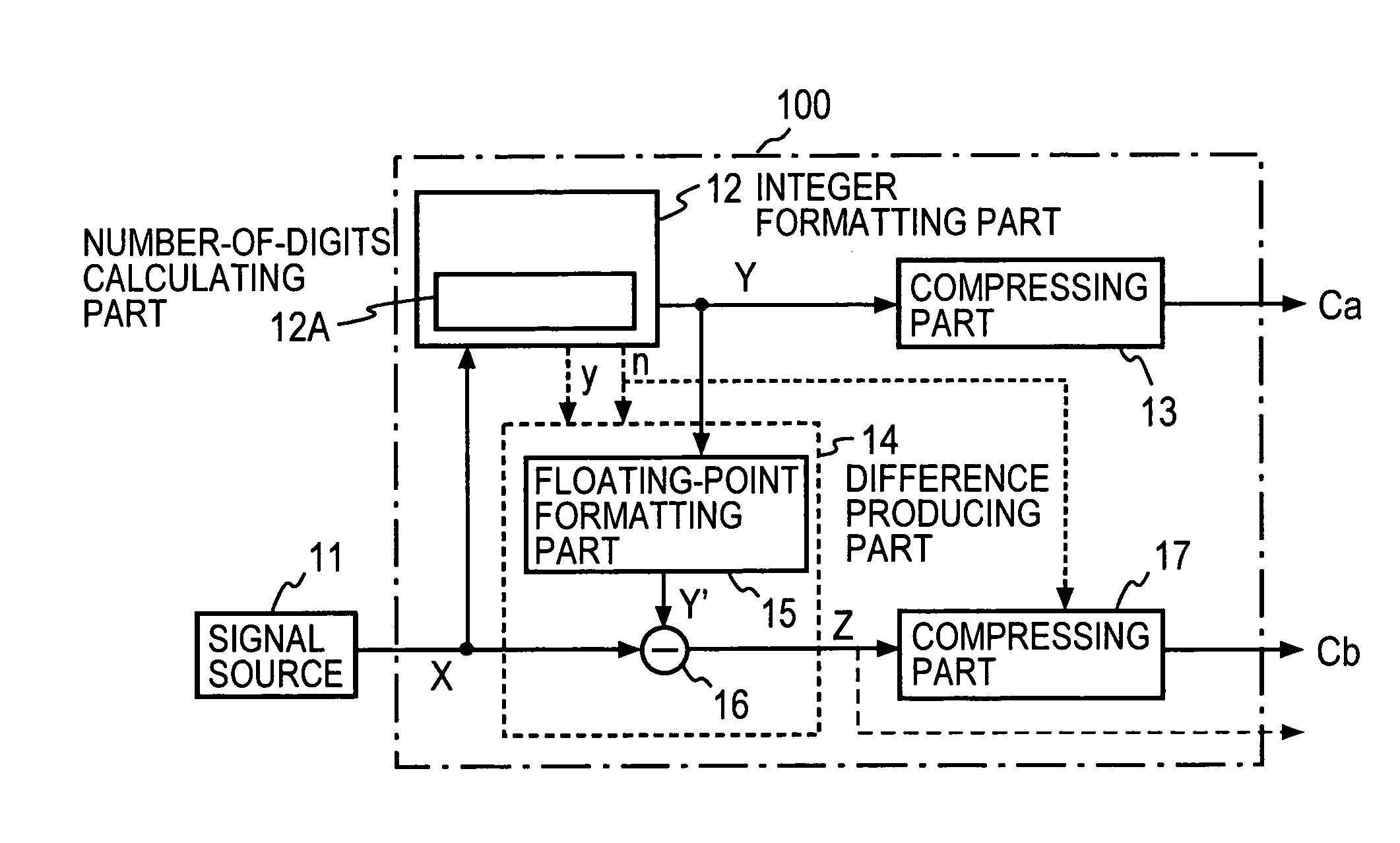
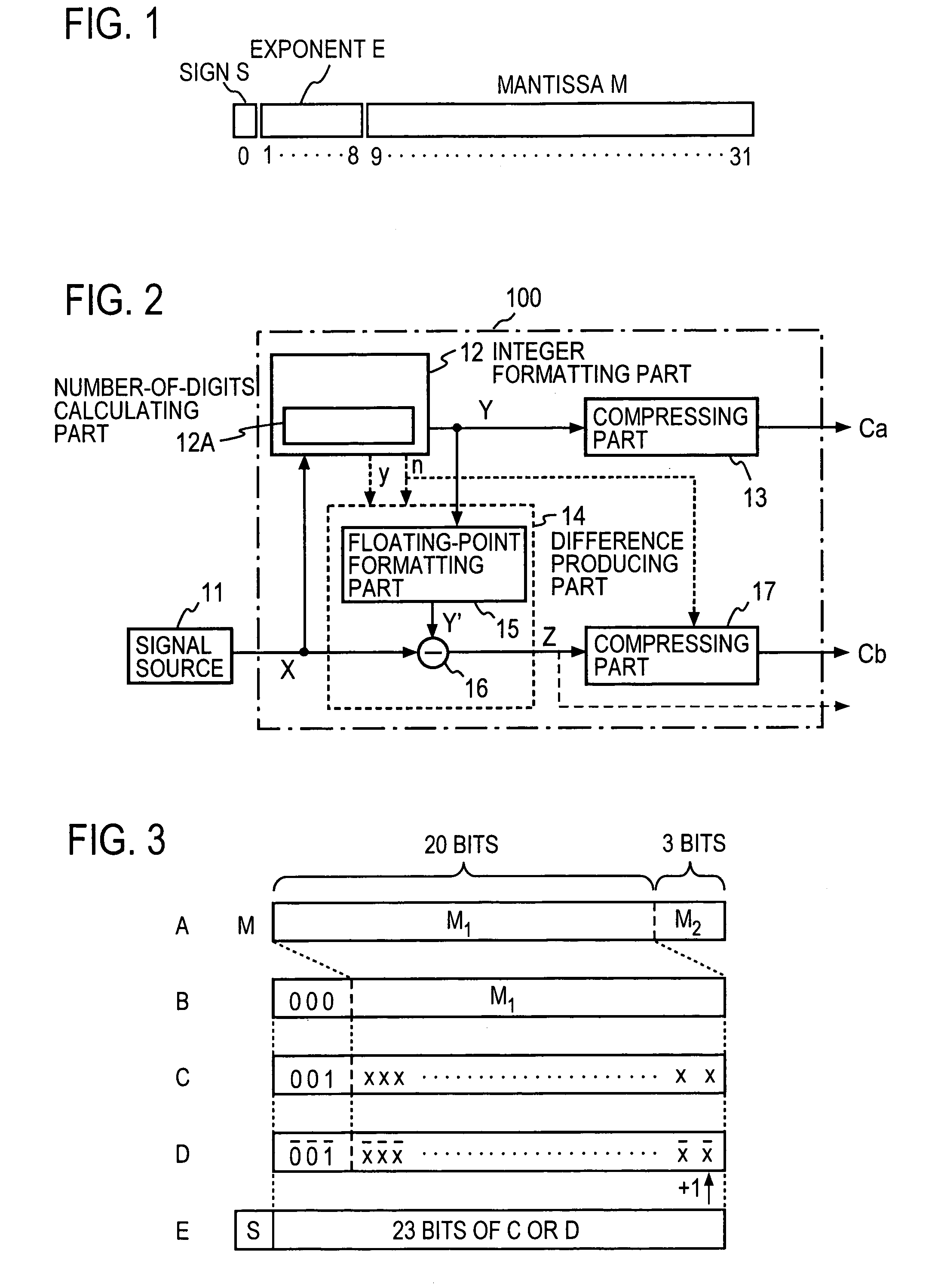
[0047]FIG. 2 shows a functional configuration of a coder according to an embodiment of the present invention. A coder 100 according to this embodiment comprises an integer formatting part 12, a compressing part 13, a difference producing part 14, and a compressing part 17. The integer formatting part 12 has a number-of-digits calculating part 12A, and the difference producing part 14 comprises a floating-point formatting part 15 and a subtraction part 16. For example, a signal source 11 outputs a music signal sample sequence as a sequence of input digital signal samples X (simply referred to also as input signal samples X, hereinafter) in the 32-bit floating-point format. Each of the digital signal samples X is produced by performing a processing, such as transformation, amplitude adjustment, effect addition and mixing, on a raw signal recorded in the 24-bit integer format and converting the resulting signal having a fractional part as a result of the processing into the floating-po...

second embodiment

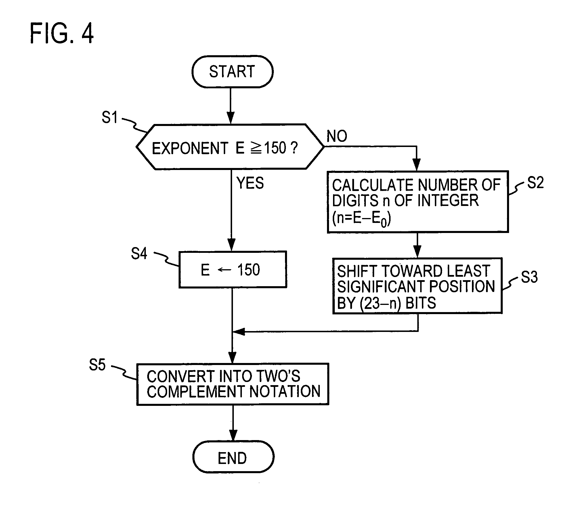
[0079]In the above description of the embodiment shown in FIG. 2, the exceptional processing is performed on a sample whose exponent E holds E ≧150. However, as briefly described earlier, digit adjustment may be performed on a frame basis to avoid the situation of E≧150. In the following, an embodiment in which digit adjustment is performed so that the maximum value of the exponents E of the samples in a frame falls within a range of 150>E≧150−K will be described with reference to FIG. 9.

[0080]FIG. 9 is a functional diagram of a coder 100 according to a second embodiment of the present invention, in which the parts corresponding to those in FIG. 2 are denoted by the same reference numerals as in FIG. 2. According to the second embodiment, a sample sequence dividing part 31 divides a sequence of digital signal samples X in the floating-point format into blocks of a predetermined number of samples or into frames, and a digit adjusting part 32 performs digit adjustment on the exponent ...

modified embodiment

[0101]As shown in FIG. 12, in which the parts corresponding to those in FIG. 9 are denoted by the same reference numerals, without performing the inverse digit adjustment of the digital signal sample Y, the digital signal sample Y in the integer format may be converted into a digital signal sample in the floating-point format by the floating-point formatting part 15, and the difference between the resulting digital signal sample in the floating-point format and the digital signal sample in the floating-point format having been adjusted in digit by the digit adjusting part 32 be determined, thereby producing the difference signal Z in the floating-point format. That is, as far as the difference producing part 14 determines, in the floating-point format, the difference signal between the original digital signal sample X in the floating-point format and the digital signal sample Y in the integer format, any of the arrangements shown in FIGS. 2, 9 and 12 can be used.

[0102]Associated wit...


PUM


Abstract

Signal samples X in a floating-point format, each of which is composed of 1 bit of sign S, 8 bits of exponent E and 23 bits of mantissa M, are converted through truncation by an integer formatting part 12 into signal samples Y in a 24-bit integer format, the integer-value signal samples Y are coded by a compressing part 13 into a code sequence Ca, and the code sequence Ca is output. According to the number of digits n following the most significant “1” in the integer-value signal sample Y, a difference producing part 14 extracts the least significant (23−n) bits from the mantissa M of the input signal sample X to form a difference signal Z, and a compressing part 17 performs entropy coding of the difference signal Z to produce a code sequence Cb and outputs the code sequence Cb. Alternatively, the difference signal Z may be output as it is, rather than being compressed.

Description

[0001]This application is a 371 of PCT / JP04 / 08726 filed on Jun. 21, 2004.TECHNICAL FIELD[0002]The present invention relates to a coding method for compressing a digital sound, music or image signal into a code of smaller information quantity, a corresponding decoding method, a coding apparatus therefor, a decoding apparatus therefor, and programs therefor.BACKGROUND ART[0003]As a method for compressing sound or image information, there is known a lossless coding method that involves no distortion.[0004]Highly compressive lossless data compression can be achieved by combining a highly compressive lossy coding and a lossless compression of the difference between a signal reproduced from the result of the highly compressive lossy coding and the original signal. Such a combined compression method has been proposed in the patent literature 1. The method, which is described in detail in the patent literature, will be described briefly below.[0005]In a coder, a frame forming part successiv...

Claims


Application Information

Patent Timeline
Patent Type & Authority Patents(United States)
IPC IPC(8): H03M7/02H03M7/24
CPCH03M7/24H03M7/40H03M7/4087
Inventor MORIYA, TAKEHIROYANG, DAI
Owner NIPPON TELEGRAPH & TELEPHONE CORP
Why Eureka
Try Eureka