Touch position coordinate detecting system

a technology of position coordinates and detection systems, applied in the direction of user-computer interaction input/output, instruments, computing, etc., can solve the problems of high energy consumption of touch position detection systems, incompatible touch position detection techniques based on frequency measurements, and useless bursts, etc., to enhance the signal-to-noise ratio of the system

Inactive Publication Date: 2007-06-12
GENERALTOUCH TECH
View PDF6 Cites 40 Cited by
  • Summary
  • Abstract
  • Description
  • Claims
  • Application Information

AI Technical Summary

Benefits of technology

[0018]In one embodiment of the present invention a touch position coordinate detecting system is provided that is based on surface acoustic waves and includes arrays of reflective patterns between a touch region of a touch panel. An initial burst that includes two frequency components is sent on the panel. The reflective arrays include two sub-arrays centered respectively at the two frequencies. A touch on the panel involves an absorption of the acoustic waves traveling in the region of the panel, and provides a localized damping in a time output signal. A time localized damping is detected for each reflected frequency components, thereby enhancing the signal-to-noise ratio of the system.

Problems solved by technology

Therefore, the technique of touch position detection based on frequency measurements is not really compatible with a manufacturing process in series with the touch panels.
If the user does not touch the panel, the bursts are launched uselessly.
It is well known that such touch position detecting systems are very energy consuming.
The problem becomes crucial when such touch position detecting systems are provided on self-service terminals in public places, for example, in airports or train stations.
If such a burst has to be launched every 0.5 millisecond, the system consumes a huge amount of energy.

Method used


Image

  • Touch position coordinate detecting system
  • Touch position coordinate detecting system
  • Touch position coordinate detecting system

Examples


Embodiment Construction

[0028]Further to the description above of the prior art with reference to FIGS. 1 and 2, the description of an embodiment according to the invention is given hereafter with reference to FIG. 3.

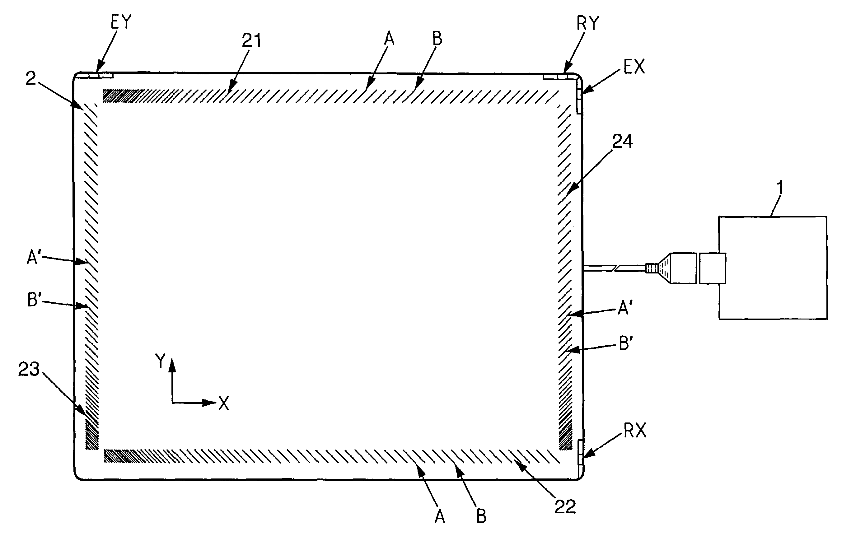
[0029]In the example of FIG. 3, the array 21 comprises first A and second B interspersed sub-arrays. The array may comprise more than two interspersed sub-arrays if a higher precision of detection is required and / or if a lower amount of consumed energy is required. The spacing n.λ1 between two consecutive patterns of the first sub-array A, taken along the X-axis, substantially equals an integral multiple of a wavelength at a first acoustic frequency f1. Moreover, the spacing m.λ2 between two consecutive patterns of the second sub-array B, taken along the X-axis, substantially equals an integral multiple of a wavelength at a second acoustic frequency f2. Therefore, the first and second sub-arrays are adapted for reflecting respectively at least a substantial part of a first frequency f1 compone...


PUM


Abstract

A touch position coordinate detecting system is provided that is based on surface acoustic waves and includes arrays of reflective patterns between a touch region of a touch panel. An initial burst that includes two frequency components is sent on the panel. The reflective arrays include two sub-arrays centered respectively at the two frequencies. A touch on the panel involves an absorption of the acoustic waves traveling in the region of the panel, and provides a localized damping in a time output signal. A time localized damping is detected for each reflected frequency components, thereby enhancing the signal-to-noise ratio of the system.

Description

BACKGROUND OF THE INVENTION[0001]1. Field of the Invention[0002]The invention relates to a touch position coordinate detecting system, using acoustic waves propagating on a touch panel.[0003]2. Description of the Related Art[0004]Touch position coordinate detecting systems are usually used, for example, in graphic display apparatuses, generally provided with a detecting system for determining the coordinates of a touch position along two predetermined axis X and Y, which are generally at right angles. A touch, causing an acoustic attenuation, is generally realized by the application on the panel of a finger tip of a user, or alternatively of a stylus (referenced ST on FIG. 1) adapted for absorbing acoustic wave energy and manipulated by the user, thus selecting a displayed menu or command. The detection of the position of the touch along the coordinates enables the system to determine the choice of the user and possibly the next graphic to be displayed. Such a touch position coordin...

Claims


Application Information

Patent Timeline
Patent Type & Authority Patents(United States)
IPC IPC(8): G09G5/00G06F3/03G06F3/033
CPCG06F3/0436
Inventor CHAO, ZHONG DEYONG, AOWEI, DENG
Owner GENERALTOUCH TECH
Why Eureka
Try Eureka