
Random number generator

a random number generator and generator technology, applied in multiplex code generation, instruments, electrical equipment, etc., can solve the problems of requiring additional hardware or processor operation to generate pseudo random sequences, difficult to detect spread spectrum signals on narrow band equipment, and the inability of an eavesdropper to intercept random sequences, etc., to achieve the effect of providing real estate and power consumption efficiency

Active Publication Date: 2007-06-12
MONTEREY RES LLC
View PDF4 Cites 27 Cited by
  • Summary
  • Abstract
  • Description
  • Claims
  • Application Information

AI Technical Summary

Benefits of technology

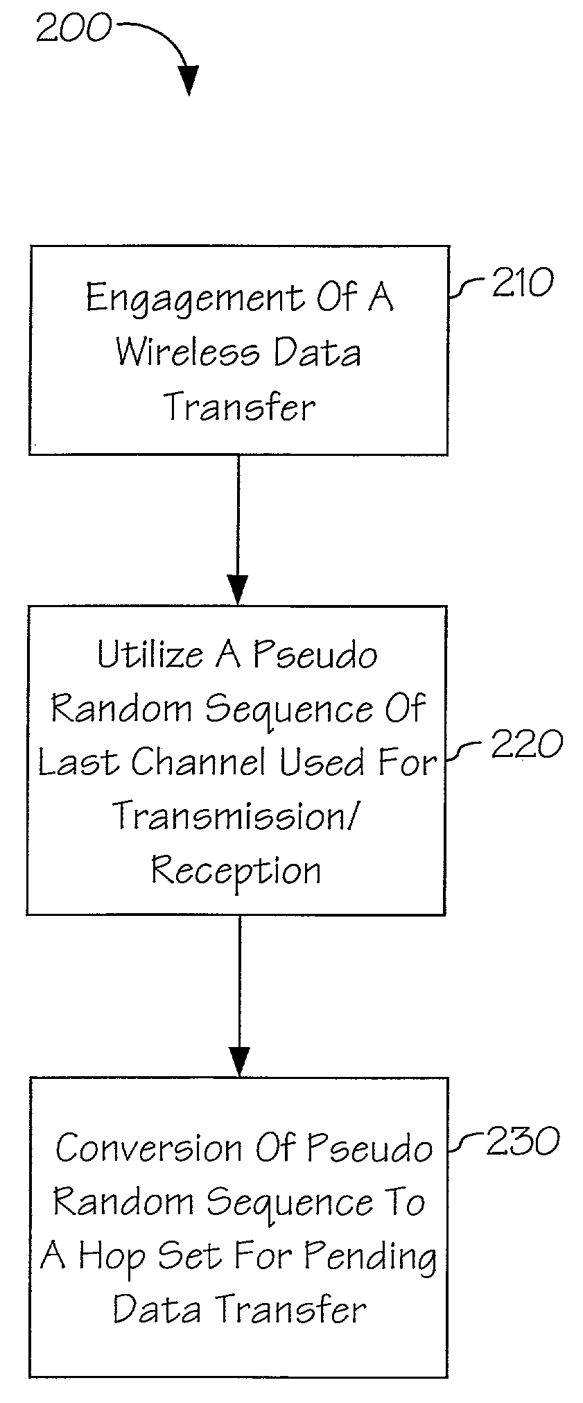
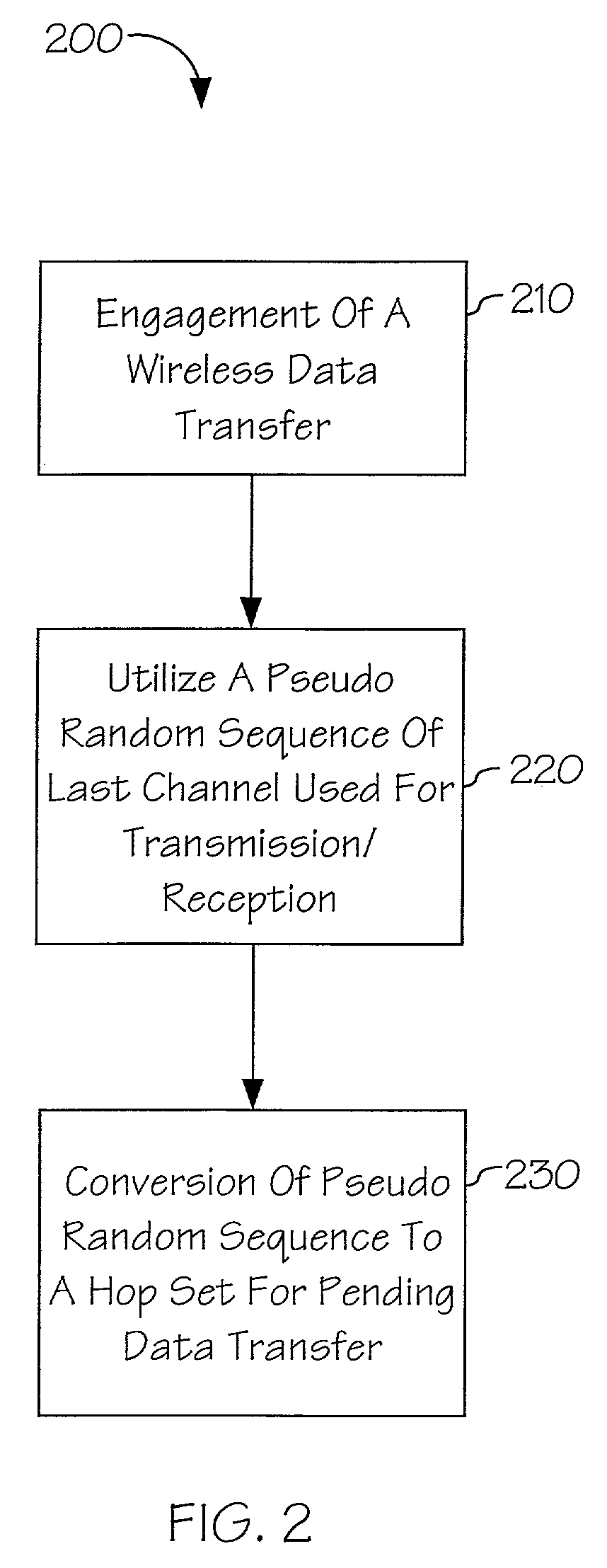
[0008]Accordingly, the present invention is directed to a method and apparatus for providing a pseudo random sequence for a spread spectrum system that prevents interception and provides real estate and power consumption efficiency. In an embodiment of the invention, the method and apparatus may generate a pseudo random sequence in real-time based on the channel location of the carrier frequency. For example, the entire band of the spread spectrum system may be scanned to detect a channel with a low received signal strength, or alternatively, to detect noise. The location of the channel, or the actual frequency of the channel, could be associated with a particular pseudo random sequence via a look-up table or similar implementation for frequency hopping.

Problems solved by technology

Spread spectrum signals are difficult to detect on narrow band equipment because the signal's energy is spread over a bandwidth many times greater than the information bandwidth.
A drawback associated with conventional schemes for generating pseudo random sequences known to the art is the ability of an eavesdropper to intercept the random sequence.
Another disadvantage to utilization of pseudo random sequences is the requirement of additional hardware or processor operation to generate the pseudo random sequences.
Thus, hardware random number generators require additional components that add cost and occupy chip real estate on a spread spectrum radio.
This requires additional processor action which increases power consumption.

Method used


Image

  • Random number generator
  • Random number generator
  • Random number generator

Examples


Embodiment Construction

[0016]Reference will now be made in detail to the presently preferred embodiments of the invention, examples of which are illustrated in the accompanying drawings.

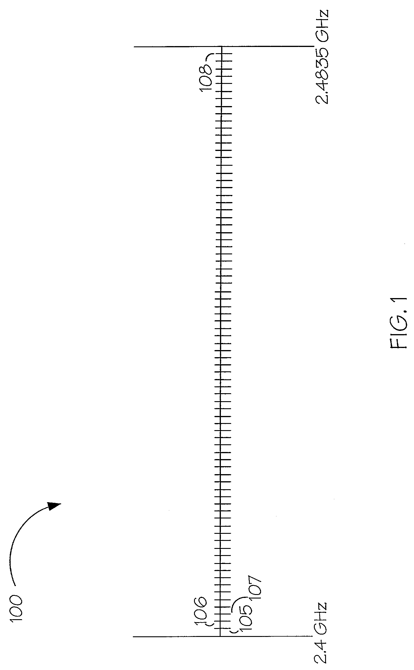
[0017]Referring to FIG. 1, a diagram representing, as an example of a frequency band, the 2.4 GHz Industrial, Scientific and Medical (ISM) band 100 is shown. It should be understood that the ability to generate a pseudo random sequence in accordance with the present invention may be employed on other types of frequency bands, however, the unlicensed 2.4 GHz band is shown for exemplary purposes. When frequency hopping spread spectrum technology is employed, the 2.4 GHz band may be divided into 79 separate 1 MHz channels 105–108 from 2.4 GHz to 2.4835 GHz. It should be understood that the ISM band is slightly modified in France, Spain and Japan but would not affect the operation of the present invention and necessarily would not depart from the scope and spirit of the present invention. Frequency hopping technology utilizes ...


PUM


Abstract

The present invention is a method and apparatus for providing a pseudo random sequence for a spread spectrum system that prevents interception and provides real estate and power consumption efficiency. A pseudo random sequence may be created in real-time by associating a pseudo random sequence of a channel location of the carrier frequency at an instant in time. For example, the entire band of the spread spectrum system may be scanned to detect a channel with a low received signal strength. The location of the channel, or the actual frequency of the channel, could be associated with a particular pseudo random sequence to create a hop set for frequency hopping. Additionally, the location of a characteristic of the spread spectrum system, such as a noise characteristic, could be utilized to determine a content of a pseudo random sequence.

Description

CROSS REFERENCE TO RELATED APPLICATIONS[0001]The present application claims the benefit under 35 U.S.C. § 119 of U.S. Provisional Application Ser. No. 60 / 291,713 filed on May 17, 2001. Said U.S. Provisional Application Ser. No. 60 / 291,713 is hereby incorporated by reference.FIELD OF THE INVENTION[0002]The present invention generally relates to the field of random number generation, and more particularly to a method and apparatus for generating a pseudo random hop set in a frequency hopping spread spectrum communication system.BACKGROUND OF THE INVENTION[0003]Wireless communications have become popular as a reliable and cost-effective alternative to hard-wire communication transfer. Along with infrared and microwave radio, spread spectrum technology is employed in many wireless communication systems. Spread spectrum is a type of modulation that scatters data transmission across an available frequency band in a pseudo-random pattern. Thus, spread spectrum employs a signal resistant to...

Claims


Application Information

Patent Timeline
Patent Type & Authority Patents(United States)
IPC IPC(8): H04B1/69H04B1/707H04B1/713
CPCH04J13/00H04B1/707H04B1/713H04J13/10
Inventor BEARD, PAUL
Owner MONTEREY RES LLC
Learn More