Table saw having a measurement and display system

a table saw and display system technology, applied in the field of table saws, can solve the problems of not having accurate measurements, unable to reset the fence, and tape measures, and achieve the effects of increasing the effective size of the table saw top, increasing the range of the sensor strip, and increasing the effective size of the workpi

Inactive Publication Date: 2007-06-19
CREDO TECH CORP
View PDF27 Cites 19 Cited by
  • Summary
  • Abstract
  • Description
  • Claims
  • Application Information

AI Technical Summary

Benefits of technology

[0017]A second preferred embodiment includes a table extension which can be moved to increase the effective size of the table saw top so that larger work pieces can be supported during cutting. In this embodiment, the fence rail is connected to an extension rail so that the fence rail moves with the extension to thereby increase the range of the sensor strip and sensing unit for providing larger measurements.
[0019]A fourth preferred embodiment includes a mounting mechanism that enables a relatively short and inexpensive sensor strip to be selectively positioned to increase the range of measurement of a fence along the width of the table saw and to adjust the measurement as a result of the position of the sensor strip.

Problems solved by technology

Most tape measures, for example, do not have accurate measurements beyond a 1 / 32 of an inch or less.
Also, if the fence is moved during other types of cuts, it is not possible to reset the fence at exactly the same position that was used for a prior cut without going through the complete exercise again.

Method used


Image

  • Table saw having a measurement and display system
  • Table saw having a measurement and display system
  • Table saw having a measurement and display system

Examples


first embodiment

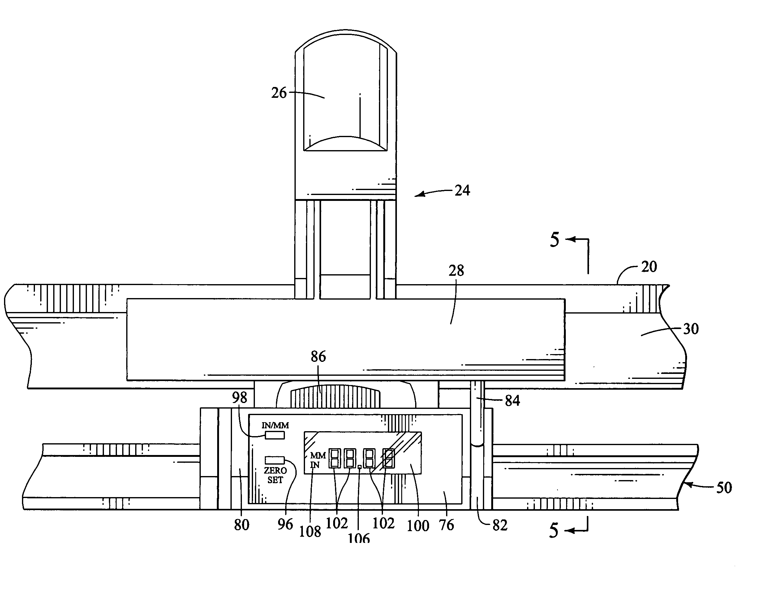
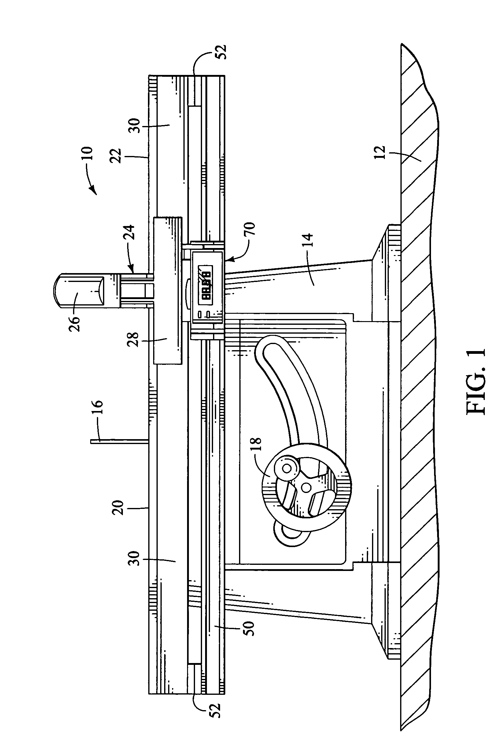
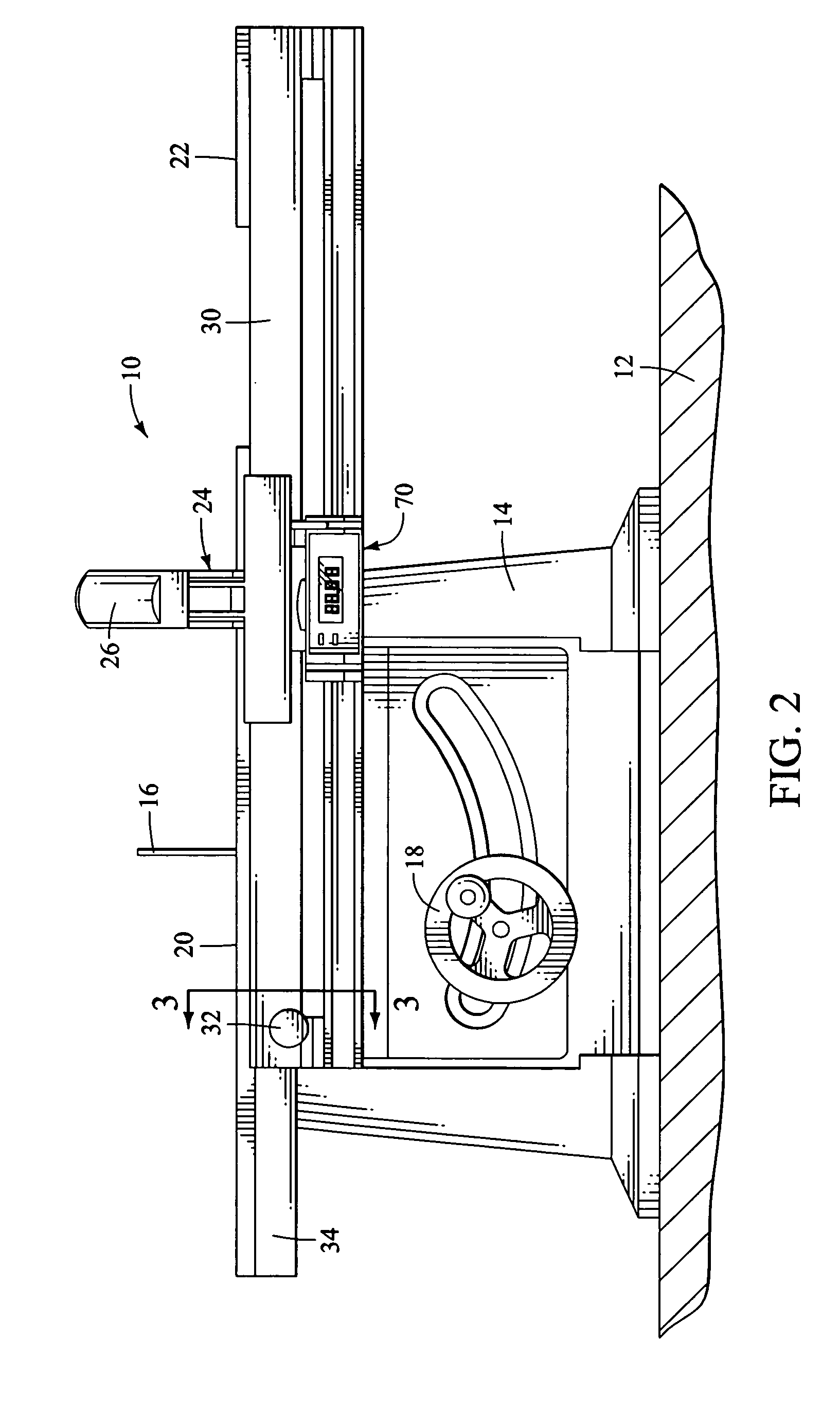
[0022]a table saw of the present invention is shown in FIGS. 1, 2 and 3 and illustrates a table saw, indicated generally at 10, of the type which is configured to be supported by a table 12 or other support structure or frame having legs. It should be understood that the table saw 10 could be of the type which has its own support stand and may be more permanent rather than the one illustrated which is often referred to as a portable saw. The saw 10 has a base 14 in which the saw motor (not shown) is located with the motor driving a blade 16, the height of which can be adjusted by conventional adjustment means (not shown) and which can also be angularly adjustable by an assembly that includes a wheel 18.

[0023]The saw 10 has a main tabletop 20, a tabletop extension 22 and an adjustable fence, indicated generally at 24, that has a handle 26 that can be raised and lowered to lock the fence in a desired lateral position relative to the blade. The fence has a base portion 28 that is slida...

seventh embodiment

[0044]A seventh embodiment is shown in FIG. 13 and is similar to the embodiment of FIG. 12, except that a rotational position transducer unit is located within a display unit module 240 has a fence 242 mounted to it. While not shown, the fence 242 is preferably removable from the module 240 and a locking mechanism is either associated with the fence 242 or the module 240. A tape 244 extends from the module 240 and is attached to a bracket 246 or the like that is attached to the table saw. This embodiment has an extrusion 248 that is similar to the extrusion 222 of FIG. 12 in that it has a lower portion 250 on which a bracket 252 is slidably attached. The bracket 252 is attached to and carries the display module 240. The operation of this embodiment is substantially similar to the embodiment shown in FIG. 12, but has the advantage that the position transducer unit is directly connected to the display unit and no independent communication capability is required.

[0045]With regard to al...


PUM

PropertyMeasurementUnit
lengthaaaaaaaaaa
lengthaaaaaaaaaa
distanceaaaaaaaaaa

Abstract

A table saw having various embodiments of a measurement and display system. Several embodiments have at least one fence rail on which a removable fence is movably supported and comprise an elongated sensor strip that is located adjacent the fence rail and a sensing unit that is supported and positioned adjacent to the sensor strip and is capable of providing an electrical signal to a display unit that is indicative of the position of the sensor unit relative to the elongated sensor strip. A processing unit is operatively connected to the sensing unit and display unit to provide a digital readout of the position of the sensing unit. A switch is connected to the processing unit and is adapted to provide a zero or reference setting position.

Description

BACKGROUND OF THE INVENTION[0001]Table saws of the type which have a circular cutting blade are well known and have been used by tradesmen and woodworkers for decades. Because they have a generally flat surface, large and small boards as well as plywood sheets can be cut to the appropriate size by typically setting a fence at the appropriate position to perform a cut along a desired line which is done by pushing the board or sheet across the tabletop and through the blade. Typically, the fence is adjustable by sliding along an elongated rail anchored at opposite ends of the table saw top, with the fence having a clamping mechanism to lock the fence once it has been placed in the desired position. Most users, when they know the width of the desired board will use a tape measure or other measure to position the fence to obtain the desired width by measuring between the edge of the blade to the fence. After the fence is in position, it is locked in place and users typically remeasure t...

Claims


Application Information

Patent Timeline
Patent Type & Authority Patents(United States)
IPC IPC(8): B27B27/02B26D7/01G01B7/04B23D47/02B23D59/00
CPCB23D47/025B23D59/001B27B27/02Y10T83/727Y10T83/7684Y10T83/773Y10T83/856Y10T83/857
Inventor OBERHEIM, STEPHEN C.
Owner CREDO TECH CORP
Why Eureka
Try Eureka